Alongside RAP’s excavations in the Rowanduz and Diana subdistricts were excavations of Gund-i Topzawa, Ghaberstan-i Topzawa, and Sidekan Bank, discussed in this chapter. These sites were excavated with the permission and direction of the Director of Soran’s Directorate of Antiquities, Abdulwahab Suleiman. Three of the sites, Gund-i Topzawa, Ghaberstan-i Topzawa, and Sidekan Bank, were revealed and damaged by contemporary construction, prompting RAP’s quick response and excavation. A discussion of the Mudjesir and Qalat Mudjesir excavations is included in the following survey chapter (Chapter 6) alongside survey results from the environs surrounding the modern village.
Gund-i Topzawa was discovered during road construction along the Topzawa Valley. When earth movers widened the existing dirt path, cutting away sections of the hillside, the machines exposed a lengthy section of the valley. Among the many graves and walls revealed during this process was Gund-i Topzawa. The site stood out for its concentration of walls and wide, thick charcoal burn layers on the associated floors. Excavation and survey uncovered at least six structures, dating from the late 2nd millennium BCE to mid-1st millennium BCE. Based on the excavation of the buildings’ rooms and ceramic analysis, these structures were farmsteads, likely part of the same cultural sphere as Muṣaṣir.
Ghaberstan-i Topzawa was a tomb in the Topzawa Valley uncovered and partially destroyed by the same road widening operation that led to the discovery of Gund-i Topzawa. Located further upstream in the Topzawa Valley, mere kilometers from the Iranian border, the tomb marked the last area of the valley before a rapid ascent into the heights of the Zagros Mountains. Its main structure was a stone-built “bee-hive” shaped tomb, with its entrance destroyed by the construction. The tomb's primary use phase was in the latter half of the first millennium, with Achaemenid material culture and a post-Achaemenid radiocarbon date. Accompanying the tomb was a small subterranean structure of uncertain use.
Sidekan Bank was a rescue operation of a small site along the main road in Sidekan, partially destroyed by the poured concrete foundations for a bank. During the laying of the building’s foundations, several large pots were cut through, prompting Abdulwahab Suleiman and the Antiquities Department to ask for RAP’s assistance in conducting a site assessment and recording any archaeological materials. The site lacked major architectural features but contained multiple surfaces, at least one with burning. A seal with indistinct iconography, made of glazed frit or some other composite material, is a indicative of Sasanian occupation and dates the site to that period.
While the original research goals of RAP did not include excavations of these sites, the ability to uncover material from multiple locations in this area provided an opportunity to understand the settlement dynamics of Sidekan. Further, three sites' accidental discoveries, unrelated to any topographical features that would have revealed their subterranean location, provided an unbiased, or differently biased, set of sites. The goal of this publication and discussion of the following four sites is to establish the chronological range of occupation in the area, the types of settlements, and their relationship to the surrounding topography.
Recording & Data Management
Excavation recording methodology for RAP is based upon the system originally used at Nippur and further adapted at Tell-es Sweyhat in Syria, led by RAP Director Michael Danti and Associate Director Richard Zettler, respectively. Context recording is based on an Operation, Locus, and Lot system. Operations are laid down over interesting features or areas suspected to contain valuable archaeological data. Often, the Operations conform to the topography of the site. This system differs from other excavation methods in which excavators subdivide the site into a grid of regular sizes based on the grid. In that system, locations are recorded using the grid’s numbering. Often in this system, the excavation trenches are placed along the grid lines. While each methodology's relative pros and cons could be discussed ad nauseam, each method has at least one point in favor of its use. The grid methodology gives more control over the size of the excavation and, when leaving a small balk between squares, guarantees a complete section to draw and record. However, using arbitrary Operation areas can better capture the full extent of the architecture or area under analysis and more quickly begin an excavation, as excavators are not required to create a grid at a site beforehand. In the Sidekan area, where our excavations are guided almost entirely by what was exposed previously on the surface, the Operation methodology captures the architecture and areas in question more fully.
Within each Operation, the contexts are recorded using Locus and Lot. Loci are primarily used for defining a discrete area, like the interior area of a room. Lots are used mainly as a vertical division, originally used to define distinct changes in soil stratigraphy but can be adapted for any change within a locus. For example, a room bounded by four walls would be one locus, and as soil changes from clay to plaster, a new lot is opened. Used correctly, this system allows for a high degree of vertical and horizontal control, describing the elevation of finds and their relationship to other areas at the same elevation. These recording fields, along with the site name, are combined to document all artifacts recovered during excavation – SITE.OPERATION.LOCUS.LOT – resulting in collections like GT.1.6.3, for example. Collection units, bags, are assigned numbers, mostly sequentially given the order of bag tags available to the excavator. The date of the excavation and excavator is included as well. Ceramics from the excavation are recorded with the Locus-Lot system and separated by day. Processing occurs off-site, in the lab or another suitable location.
While the data were primarily recorded using analog methods and digital photography, I processed, organized, and analyzed the material using a relational database. The software used was Airtable, a “freemium” (i.e., free until hitting storage allowances or other limits) cloud-hosted database. Utilizing a relational database with “one-to-many” connections allowed adding not just the entire corpus of excavated material but material collected on survey, survey information, and related info from other sites. Throughout this research, beginning in 2013 up to the present day, advances in technology and freely available software changed the possible limits of what individual scholars can digitally create. Specifically, in the case of databases, the rise of “No-Code” software platforms enabled the creation of advanced databases with only the basic understanding of lists and structures. Airtable is only one of the vast growing catalog of No-Code software platforms (nocode.list 2019). Those changes, still ongoing and accelerating, reframe the digital divide in scholarship and alter how archaeologists can conduct research.
For four decades, the field of Digital Humanities grew as a way for humanists to confront the growing prevalence and power of digital tools in the academy (Burdick et al. 2012, 10). While some embraced this change, others simultaneously adopted the label while decrying technology's imposition into the rarefied study of the humanities (Khanwalkar 2017). While there is no single definition of Digital Humanities, one offered by Burdick et al. captures the ambiguity and changing nature of the sub-discipline: “the area between the humanities, in its full richness, and ‘the digital.’ The digital is taken to include information technologies, digital media, and different types of digitally-enabled modalities, tools, and expressions” (2012, 5). Explicit in that definition is the delineation of ‘the digital’ as a discrete field, in opposition to the humanities. Simultaneously, however, many digital humanists recognize that technology is only a tool and that use of that tool is what makes a humanist a digital humanist. With that expansive definition comes the insight that digital humanities are as much a question of salesmanship as it is a scholarly debate (Kirsch 2014).
There was a time, as the field of Digital Humanities grew, in which the ability to use digital tools required discreet skills. As Drucker emphasizes, tools are not neutral artifacts, and digital tools are far from exempt from that reality (2020). Thus, while there is value in understanding these tools' power and capabilities, as any tool in academia, the debate within Digital Humanities has too often been whether humanists should learn the skills required to build and operate these tools (Kirsch 2014) fully. For specific digital tools, knowledge of the technical foundations or use of coding is essential, while others only require a basic understanding of the logic. After the mass migration to remote and digital work beginning with the outbreak and subsequent isolation caused by COVID-19, the digital is fully ensconced in every aspect of modern lives, including humanities scholarship. Thus, sequestering the Digital Humanists from humanists is no longer a necessary division and serves only to add unnecessary barriers for scholarship writ large.
One of the most fundamental tools for archaeologists, either digital or analog, is databases. Databases are how we mediate the objects in the ground and transform raw archaeological material into the data underlying interpretations and conclusions. Whether the databases are advanced, fully relational systems requiring a dedicated technician, a series of computer folders, or hundreds of drawers of physical find cards, how we store and structure data informs how we analyze and understand the past. Since at least the 1980s, archaeologists have attempted to build digital ceramic databases, in part, with the dream of creating fully connected datasets across sites and regions (Blakely and Bennett 1989). In many ways, databases will always be an interface between the researcher or excavator’s chosen research question and the available material (Bennett and Blakely 1989, 8). A good report and database rely on a clear understanding of the objectives before beginning the research (Peacock 1977, 33). While traditional relational databases require a fair amount of foresight, planning, and maintenance, no-code databases allow for agile input and data manipulation. Their ease of use is spurring a renaissance in digital access, not just in academia but in the world writ large (Gaggioli 2017). No-code databases allow archaeologists to manipulate data as the research questions change, a capability previously out of reach for individual researchers. Further, the ease of the software platforms makes the initial collection of data digitally far easier.
As digital analysis tools become more accessible and affordable, a corresponding problem is their constant evolution and changes, creating a possible future in which corporations control and can delete entire databases. Thus, archaeologists must consider digital archival reconstruction in parallel with publishing final reports using these advanced digital tools. For example, while the Airtable database provides easy access to related contexts and artifacts, the system's fundamental architecture is no different from the basic system of card catalogs. By downloading Comma Separated Value (.csv) files that provide the same information in raw text form, researchers can submit that data to a repository in the university, so future scholars can reconstruct the archive – not unlike the hordes of graduate students in recent decades who spent countless hours going through card catalogs and paper records to reconstruct legacy excavation data. Accompanying this dissertation’s figures, appendixes, and online material are folders representing the raw data.
The Airtable database structure is fundamentally based on the field recording structure with progressively decreasing levels of detail. At the highest level is the site – sites located on Survey are stored alongside the excavated material from Gund-i Topzawa, Mudjesir, Ghaberstan-i Topzawa, and Sidekan Bank (although not all sites are published in the accompanying online database). The Context table includes all published sites’ Operation, Locus, and Lot, with each record a distinct combination of the three dimensions. Bags, an additional table, record the excavated material related to each context, mirroring the physical bags. Each context’s day and type of material (bone, pottery, charcoal, etc.) merited a unique bag number. A further level of detail was individual sherds related to their original bag number (ex. 627.4 represents one of at least four sherds from Bag 627). Providing a linkage between these tables is the Phases table, representing the chronological and stratigraphic phases generated through post-excavation analysis. An additional feature of the database is the addition of typologies – both the typology created to organize the excavated ceramics and typologies from comparable projects that allow for quick comparison of material. The intention of the publication of the vast quantity of excavated material is, in part, to promote transparency of source material, in part to allow greater and easier access, and in part to enable future scholars’ research projects utilizing the material published as part of this dissertation.
Gund-i Topzawa
Of the multiple sites excavated by RAP over four seasons, the most significant and complete is the site of Gund-i Topzawa (36.81750 N, 44.73472 E). As mentioned previously, large-scale road widening operations from Sidekan up to the Kelishin Pass cut into the hillsides above the Topzawa Çay, exposing a multitude of archaeological materials. The most extensive of these sites was Gund-i Topzawa, a series of houses along the valley's hillslopes. The site is noteworthy for its location along the primary throughway from the town of Sidekan to the Iranian border.
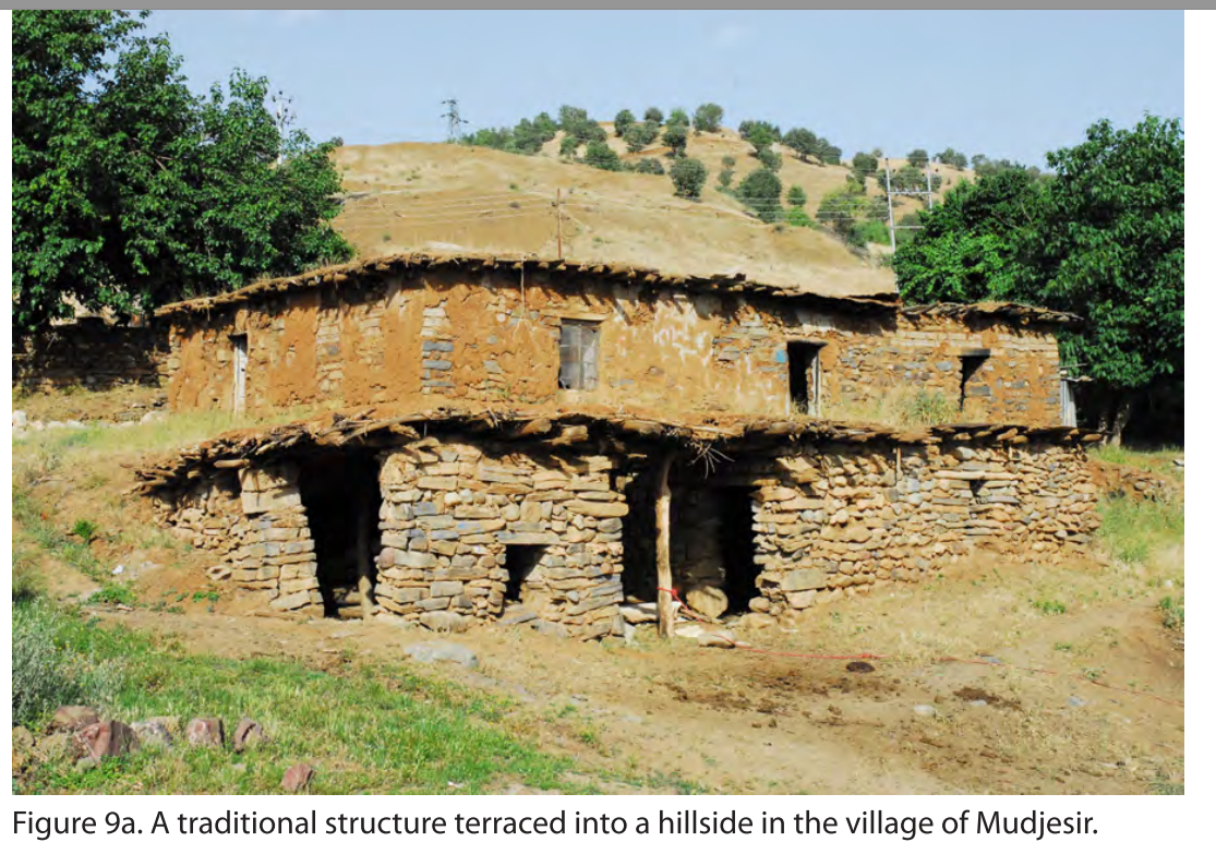
Gund-i Topzawa lies at the inflection point where the hill’s slope meaningfully increases. The valley’s wide basin below the site allows for agriculture, including plowed fields along the Topzawa Çay and orchards along the slightly steeper banks above the lightly sloping floodplain. Above these orchards, at the line of the modern road, the valley's large hills begin quickly sloping upwards at about 18°. Gund-i Topzawa and the other sites exposed in widening the road lay at this change in slope. This location's significance will be discussed further in the Survey Chapter, but comparable modern and ancient sites in Sidekan and Kurdistan are often built at this slope inflection point, cut directly into the hillside. Modern houses at Choman are characteristics of this style (Figure 4.1).
Gund-i Topzawa is 20 km from the Kelishin Pass as the crow flies, but much further when taking the arduous journey by foot or vehicle. In antiquity and modern periods, this route forms an integral connection between the two sides of the Zagros Mountain chaine magistrale. In addition, the site is a moderate distance from the known occupation centers, about 8 km from modern Sidekan, 13 km from Old Sidekan, and 11 km from Mudjesir, likely requiring at least a half day’s walk to reach these destinations. This distance from population centers defines Gund-i Topzawa as an outlying or rural settlement. Thus, determining the site’s architectural and material arrangement as well as its relative wealth and status helps elucidate the relationship between the central occupations and rural regions.
class="w-full max-w-3xl mx-auto border border-white/10 group-hover:border-[var(--color-brand-orange)] transition-all"
loading="lazy" />
Figure 4.1: Traditional Building at Mudjesir
(click to enlarge)
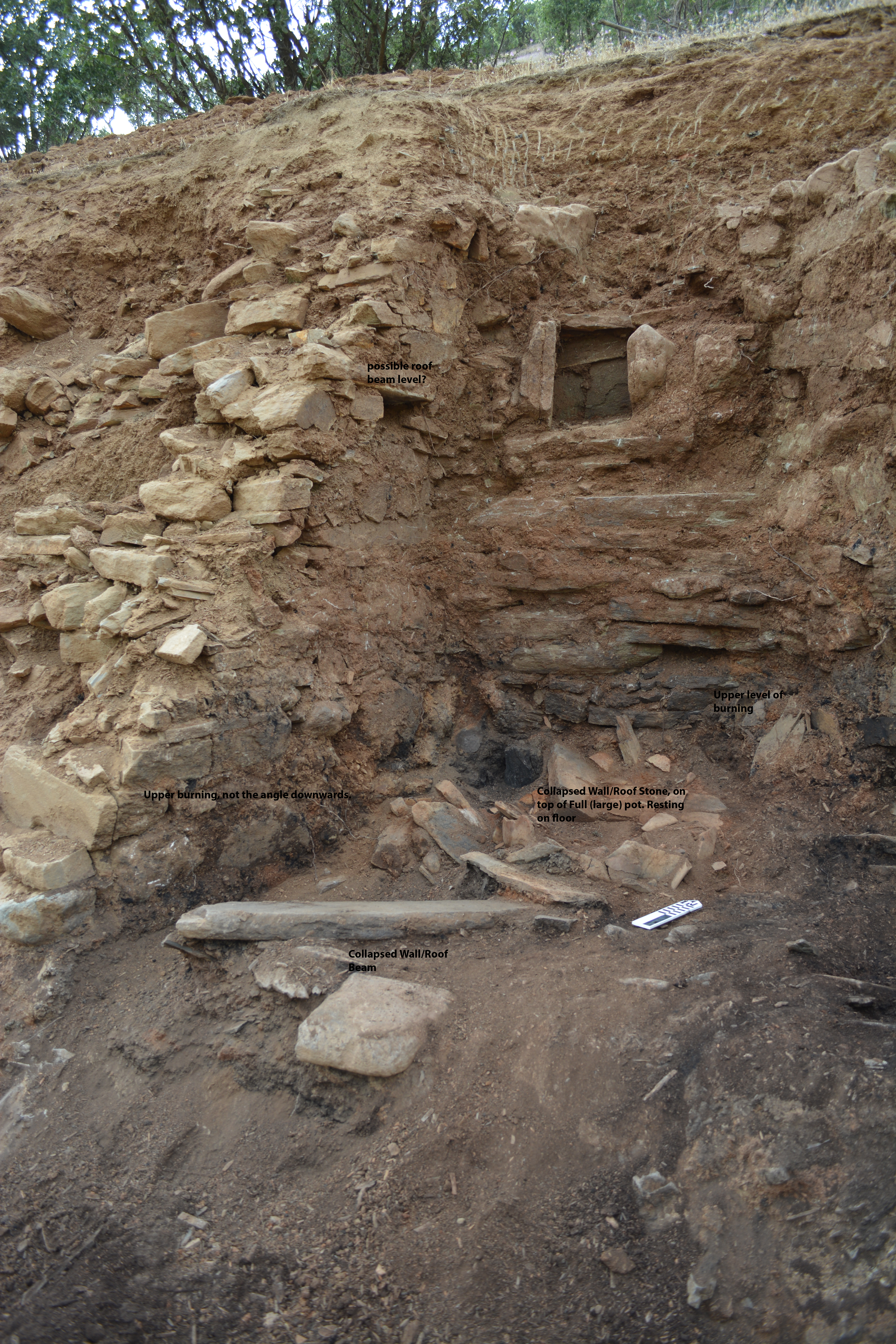
In 2013, after the construction teams moved along the Sidekan-Kelishin Road, cutting into the hillside and exposing archaeological remains, Director Abdulwahab Suleiman asked a portion of the RAP team to assist in surveying the damage. Large stone walls, along with the thick and lengthy layers of burning, immediately attracted our team's attention as they surveyed the road cut by automobile. In the season’s waning days, Dr. Michael Danti and Dr. Darren Ashby recorded the exposed section of Gund-i Topzawa. It measured 100 m along the length of the road cut, attracted attention, and necessitated documentation. In addition to recording the site's exposed section, the team recovered charcoal samples and sent three promising samples to the University of Arizona AMS Laboratory for testing. While two further excavation seasons would elucidate the relationship between these walls, floors, radiocarbon samples, and occupation phases, this section provides an overview of the overall site’s layout (Figure 4.3).
Gund-i Topzawa, while discussed as one site, is more accurately two clusters of buildings, with a virtually empty middle consisting of only a few fragmentary structures. Gund-i Topzawa East (GT-E) is about 30 m long and contains two clear buildings, Buildings 1-E and 2-E, with some undefined connection between them. Gund-i Topzawa West (GT-W) begins about 35 m west of the westernmost wall of GT-E. GT-W consists of four buildings, Buildings 1-W, 2-W, 3-W, and 4-W. The intermediate space between GT-E and GT-W, aligning with a bend in the road, has a few traces of architectural features. Only one small possible structure was defined. It is an unnamed structure with two walls and a small, 2 m wide area with significant burning. There are no other traces nearby, and this structure was not investigated further. This gap in structures may be because of the hill's slope above, with a slight impression that would lead to increased rainfall and runoff, making occupation or construction unnecessarily onerous. In this portion of the road cut section and at other points along the construction cut were destroyed or damaged graves believed to date to the Islamic period. The construction method, gravestones, and depth below the surface provide evidence of this dating, but our team did not investigate these graves apart from recording their existence and locations.
RAP excavated Buildings 1-E, 2-E, and 1-W, collecting large quantities of pottery and other finds, as well as multiple charcoal samples. Building 1-W dates to three separate periods: Phase A, the earliest level built below the structure of Phase B, to the late 2nd or early 1st millennium, likely Iron I or LBA; 1B, the main structure, dates to approximately the 7th-8th centuries B.C.E., Iron III, contemporary to the Urartian Empire to the east and the Neo-Assyrian Empire to the west; Phase C, the final squatter phase in the Achaemenid Period, Iron IV. The excavation’s radiocarbon samples, combined with the 2013 section cleaning samples, provide a possible breakdown of occupation periods at the site. Radiocarbon dates from Building 1-W suggest the main building’s main phase, Phase B, was destroyed sometime in the first half of the 8th century (roughly 800-750 BCE). From the site’s eastern portion, Building 1-E’s single carbon sample dated from ~1213-1127 BCE. The neighboring Building 2-E had two carbon samples, one dating to 1050-925 BCE and one to 925-825 BCE. The full analysis of the carbon samples and the implication for the site’s chronology and occupation phases are discussed in detail below, but the overarching conclusion is Gund-i Topzawa was a collection of buildings built into the hillside over centuries. Although there is some evidence for reoccupation and reconstruction of the same buildings, most reoccupation appears to be new homes constructed alongside destroyed ones. While the range of dates covers multiple centuries, they correspond to the main historical period at Muṣaṣir.
After the promising information from the limited section cleaning and carbon sampling in 2013 at Gund-i Topzawa, excavations began in 2014. All the excavations took place in 2014 and 2015, with the bulk of Building 1-W and limited work in Buildings 1-E and 2-E. The extensive exposure of walls and burnt floors of Phase B in Building 1-W revealed by the construction activity led to the focus on that structure. Given the nature of the Gund-i Topzawa – a 4 m+ tall section cut into a steep hillside with much of the architecture visible – the excavation methods were somewhat unconventional. Rather than lay down a rectangular trench of predetermined and arbitrary dimensions, the team defined the walls' limits and excavated the area within the walls. While this excavation method allowed for increased certainty in the plan of action, it resulted in excavated areas completely circumscribed by stone walls. Thus, some of the sections that may have been useful in understanding the exact relationship between collapse, walls, and surfaces, were removed. Despite that difficulty, the excavation resulted in a clear picture of a structure used for domestic purposes and destroyed in a fire.
Building 1-W
##### Architecture & Stratigraphy
Building 1-W’s primary use phase dates to the 8th century B.C.E., confirmed by radiocarbon dating and ceramic parallels (Chapter 4, Gund-i Topzawa Radiocarbon Dating). Two additional phases bracket the main occupation: an earlier phase, revealed during an excavation in the road, and the late phase, consisting of at least one burial on top of the collapsed structure. I dubbed these three phases A, B, C, with A representing the earliest remains, B the main Building 1-W, and C the later burial. In addition, a small squatter occupation existed after phase B's destruction but before the burial in phase C. That occupation consisted only of ash and pottery but was not deliberately arranged and poorly recorded, thus not requiring a distinct phase. While our excavations revealed nearly the full extent of Building 1-W Phase B, the extent and nature of architecture in Building 1-W Phase A are mostly unknown. Thus, an analysis of the architecture must begin with Building 1-W Phase B, then continue backward and forward in time to reveal the preceding and succeeding periods.
Building 1-W Phase B
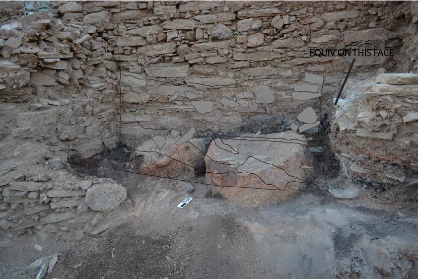
Building 1-W Phase B, a.k.a., Building 1B, consisted of three rooms: Rooms 1, 2, 3 assigned from east to west (Figure 4.3). Room 1 and Room 3 abutted secondary deposition material that divides the structure from nearby walls, thus the building’s exterior walls. The space between Room 3’s western wall and the adjacent Building 2 was less than a meter. Given the absence of dense layers of charcoal, like that in Building 1B, along with the minimal finds, this area was an outdoor space between buildings. The area to the east of Room 1’s angled wall lacked any of the distinctive burning of Building 1B, and no walls were nearby this eastern extent of the building. A small excavation into the north of the walls, directly into the hillside, uncovered a small collection of walls but lacked any significant connection or continuation to suggest a continuation of the building into the hillside.
Building 1B’s walls were constructed with horizontally laid large stone slabs, interspersed within many small stones and chippings. This technique is typical for a wide variety of ancient and modern structures. Stone chippings, small and slender bits of slate, fill in the gaps between the larger stones. Comparing the walls of Gund-i Topzawa to contemporary houses, the stone construction bears numerous similarities (Figure 4.1). This serves as evidence for the type of construction well suited for this area and the materials available. The combination of construction technique and its poor location at the base of a hillside precluded its use as a defensive position. This mixture of stone slabs and small chippings was an easy and convenient way for constructing large walls with minimal effort, though its dry-laid nature does come with risks for a structural collapse. Further, comparing Gund-i Topzawa to comparable house construction in the Sidekan area, buildings' ground floor often served as an open storage and production area. The rooms’ proposed functions at Gund-i Topzawa align well with that interpretation. Large bedrock outcroppings, unremoved before construction, jut into the living space of the ground floor rooms are features that correspond well with the rooms’ proposed use for storage and production.
Rising about 3 m from its excavated base to the exposed top was the rear wall at the north of the building (Wall 1), a central structural feature of the site. Clearing the top of Wall 1 revealed a single interconnected wall running across the entirety of the building, with most of the wall resting on the bedrock foundation below. Three other walls jutted out perpendicularly from Wall 1. The eastern exterior wall (Wall 2) angled northwest-southeast, and two north-south walls (Walls 3, 4) abutted the north wall, forming two rooms, while the exterior north-west wall (Wall 5) formed the western exterior of the building (Figure 4.3). The road widening operation damaged all of these perpendicular north-south walls, though it is nearly impossible to define how far the walls initially extended. Notably, Wall 4 contained a doorway between Rooms 2 and 3. The wall ran directly up to Wall 1 but did not join. Room 1 may be a later addition, with Wall 3 as the original exterior wall, or its construction was contemporary but added on as a distinct semi-outdoor occupation space. Building 1B’s walls were built, at least in part, on bedrock or utilized bedrock as a foundation. Northern sections of all the walls were perched on these unique bedrock spurs. This construction, a necessity caused by the substantial and irregular outcroppings of bedrock in the area, weakened the walls’ structure, evidenced by cracking and slumping between the bedrock and non-bedrock foundation points. The individual room’s construction revealed the usage patterns of the complex and the site's chronology.
Room 1 was a triangular space about 2.05 m wide (E-W) at its widest point and 1.4 m long (N-S), with its two remaining walls converging in the north. At the rear of Wall 3, the tallest point of the room measured 13 courses of stones in height. At the convergence of the three walls, the lower courses of Wall 2 curved inward towards Walls 1 and 3. The lower, curved section of Wall 2 ran directly against an outcropping of bedrock below the northernmost section of Wall 3. All of Wall 3 was built on bedrock, with the wall's rear stepping up one course where the bedrock rises.
Above the wall's curved section was a small niche, its base 1.6 m above the room’s floor. The small box's left wall had leaned inwards and turned, creating a space 25 cm wide at the front and 42 cm wide at the back, with a small stone slab serving as a roof for the niche. The box's base was a stone slab, spanning both sidewalls' width but resting on a collection of soil fill and small stones above curved courses of Wall 1. On the left and right sides of the niche were small and moderately sized stones. At approximately the same elevation, 1.6 m above the floor, was a small gap in the stones of Wall 3. Far smaller than the stone niche, this space measured one course tall, approximately 10 cm, by ca. 40 cm wide. From above, there was a noticeable gap between the corner of Walls 1/3 and Wall 2b (Figure 4.4). Below the niche, however, Wall 2 runs up against Wall 1.
Figure 4.4 not yet available
class="w-full max-w-3xl mx-auto border border-white/10 group-hover:border-[var(--color-brand-orange)] transition-all"
loading="lazy" />
Figure 4.4: Top-down View of Room 1, Gund-i Topzawa Building 1-W Phase B
(click to enlarge)
Room 1 had several notable features that provide clues to the activities performed in the room in antiquity. Two or three large pithoi were in the northeastern rear of the room. Two of them rested on the floor at the northern end of the room and were propped up by several stones around their base (Figures 4.5, 4.6). One of the pithoi (Plate 44.2) had thick walls of over 5 cm, and another (Plate 44.1) had thinner walls with a very elongated and flat rim. These vessels' total capacity could not be determined with the number of sherds and the positioning, but both stood at least 60 cm or higher, given the rim sherds and the connected pieces. The third pithoi may exist, but the rim sherd lacked sufficient preservation to confirm that designation. Nearby these pithoi, in the southeast of the room, was one large fragment of a tannur. Given its findspot, directly next to the destruction caused by the road construction, further fragments were likely destroyed or removed in that modern process.
class="w-full max-w-3xl mx-auto border border-white/10 group-hover:border-[var(--color-brand-orange)] transition-all"
loading="lazy" />
Figure 4.5: Room 1 Pithos (Plate 44.2)
(click to enlarge)
Figure 4.6 not yet available
class="w-full max-w-3xl mx-auto border border-white/10 group-hover:border-[var(--color-brand-orange)] transition-all"
loading="lazy" />
Figure 4.6: Room 1 Pithos (Plate 44.1)
(click to enlarge)
The room's western side did not contain large pithoi and pots like the east but was distinguished by large amounts of ash. South of the northwestern corner of the room was a large hearth with a heavy concentration of ash. Roughly circular, it measured 22 cm N-S, 25 cm E-W by 5 cm deep. Its cross-section showed a series of striated ash lenses above the floor. Directly to the north, in the northwestern corner, was an additional concentration of ash but dispersed over the floor’s surface, likely originating from the hearth. A spindle whorl, Object 525, was recovered in the southwest of the room, near the hearth. The object was only partially completed, as the parallel holes on either side of the clay disk did not fully connect. In the center of Room 1’s floor was the largest concentration of burnt charcoal material.
The original floor of Room 1, below the final occupation surface of Building 1B, was a reddish clay with small stone splinters integrated into the surface. During the destruction event, the floor in use was light brown, also with stone splinters, and heavily burned. A 1 cm thin dark yellow cover of silt lay on top of the floor, and a 27 cm thick layer of burning and stone collapse sealed the final occupation in this room.
Fortunately, the catastrophic conflagration event at Gund-i Topzawa resulted in a bounty of archaeobotanical material. Most of the recovered and analyzed archaeobotanical samples came from the excavations in Room 1, and their analysis can help reconstruct the purpose and function of the room. Five samples in Room 1 had significant seed evidence. A wide variety of species were present, including grains, legumes, and a wide variety of fruit, including grapes. In addition, there were many types of weeds commonly found in grain stores in the later processing stages. Of the cereals, barley was the most common, with 23 grains in one sample alone. There was, however, little evidence of cereal processing, with only a few rachis fragments. Along with the cereals were pistachio, rubus, fig seeds, and grapes, as well as several legumes, including field peas (Proctor and Smith 2017).
The high number of grape seeds and the associated components of the plants is striking. All of the Room 1 samples contained at least ca. 20% grape, with two containing more than 75% grape. The samples included large and small grape pips, intact fruits, grape skin, and pedicels, the small stalks that hold grapes into the bunches. The pips were combined with skins, pedicels, and the occasional intact fruit (one intact grape in both samples 1099 & 508). The number of pedicels with pips can be indicative of fresh grapes or raisins. Margaritis and Jones’(2006) experimental study of wine production noted the proportions of pips, pedicels, and skin fragments that often accompany wine production. In addition, by charring raisins and fresh grapes and examining the skin under a scanning electron microscope, they were able to identify subtle differences. Examination of the grapes' charred skin at Gund-i Topzawa was inconclusive, although it did not preclude an identification as fresh grapes for wine. Proctor (Personal Communication) does note, however, that Gund-i Topzawa has no apparent wine processing or production tools.
The samples' specific location and their relative amounts of archaeobotanical material in Room 1 may provide clues to the room's activity and the vegetation surrounding the site. One sample (505) had an incredibly high proportion of grape remains, over 85%. That sample originated from the ash lens in the hearth. The remaining seeds in the sample came from legumes. The other sample with a high proportion of grape remains (1083) had ca. 75% grape, with 10% weeds and small amounts of cereals and legumes. We do not have its exact location, but it came from around the back pithoi, at least 30 cm above the floor. Proctor suggests it came from the upper layer of collapse and burning from a probable roof rather than from the pithoi. One sample with a more secure location (508) had a high percentage of cereal, approximately 75%, with 20% grape. It was collected in the collapse directly above the surface next to one of the rear pithoi, possibly reflecting the contents of the destroyed pithoi. Sample 1099 was collected nearby, in the same loci, but contains over 50% weeds and ca. 25% grape. The findspots’ relationship to weeds and grapes complicates any interpretation of wine production. The high proportion of weeds indicates cereal processing, as well as a possible mud roof covering that fell into the room upon the building’s destruction.
The limited vessel types in Room 1 are quite instructive on its possible use (Full typology: Appendix A). For one, bowls dominate the room’s assemblage. Almost half of the room's diagnostic sherds (10 out of 27, 37%) were bowl rims. Further, these vessels were of broadly similar types, carinated bowls. Three were Bowl 3 types, carinated with a deep body, while five were carinated with much shallower bodies (types 6a, 6b, 7). The two remaining bowls were more rounded but had the slightest evidence of carination (types 8 and 11b). All of these bowl sherds were either in situ on the floor of the room or in the collapse immediately above the floor. The second most common type of pot in the room was holemouth jars. All but one of these examples came from either the floor itself or the context directly above the floor and largely clustered in the southwest of the room, around the area of the tannur fragment.
Table 2: Distribution of Sherd Vessel Types, Gund-i Topzawa Building 1-W Phase B
To the west of Room 1 is Room 2, the largest space and primary focus of the excavation. Measuring 3.7 m wide (E-W) by about 3.5 m deep (N-S) at its widest preserved point, this space is connected to the eastern Room 3 by a doorway in Wall 4. Wall 3 divided Rooms 1 and 2, and the surviving section of the wall was built on the same bedrock outcropping noted in Room 1. The wall is twelve courses tall in Room 2, as the floor in Room 1 is approximately one course lower than Room 1’s floor. The corner between Walls 1 and 3 was bonded, as evidenced by a top-down view (Figure 4.4). The tallest remaining portion of Wall 1 was in Room 1, rising the full 1.6 m. Beginning in the eastern corner, next to Wall 3, Wall 1 was constructed on bedrock for the room's width. Wall 4 ran up against Wall 1, with no discernable joins but some minimal connection. The northern portion of Wall 4, ca. .75 m, was built upon the same outcropping of bedrock as Wall 1 before stepping down ca. 30 cm and built on ground level. At this step-down, the wall showed a crack, leaning southwards towards Doorway 1. Doorway 1 was 2 m south of Wall 1 and 76 cm wide. The northern jam of the doorway was 10-15 courses high, with the southern jam half as tall as a result of the earth mover’s angled destruction. Less than 50 cm of Wall 4 remains south of the door jamb. A jar was on the door sill, smashed by rocks falling from the building’s destruction. The southern part of the wall was ca. 60 cm wide. Neither Wall 3 nor 4 showed evidence of beam emplacements.
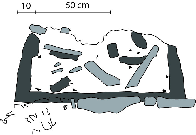
In the center of Room 2 was a large, flat outcropping of bedrock with two unique clay features, along with storage vessels. Measuring 2.8 m wide (E-W) and approximately 1.8 m deep (N-S), the bedrock under Wall 3 continued southwest into Room 2. It filled the northeast corner of the room and extended about two-thirds of the room to the west. The bedrock was a slate-like, highly brittle composition. While substantial, this material had a highly irregular and unlevel surface. To make a level platform, the inhabitants of Gund-i Topzawa seemingly laid larger flat stone slabs to remove some of the irregularities. Covering these stones was a hardened clay surface layer. On top of this platform were several features, the most notable of which were the two large round clay features.
The clay features were built on the bedrock platform's stone surface, with the thin layer of red clay surface visible in places. While the diameter of the two features differed slightly, their descriptions are mainly similar. The western feature was between 80 – 90 cm in diameter, while the eastern one measured slightly over 1 m. Vandalization of the western feature damaged its sides and led to the team sectioning and investigating the interior. It was preserved 32 – 40 cm high on its exterior, and the height of the interior was between 26 – 32 cm. The walls were constructed with red clay tempered with stone, hardened through burning, and measured 8 – 10 cm at the base. The walls were slightly concave, with an 82° angle turning inwards to a roughly 70° angle 20 cm above the base. There was no evidence in the section that the original feature was enclosed at the top. The fill consisted of fragments of clay walls, stones from the building’s collapsed walls, and charcoal specks. The clay feature’s base was the same clay material as the sidewalls but only 3 cm thick. The maximum volume of the preserved interior space was approximately 203 liters. However, the sidewalls likely extended another 5 – 10 cm above the preserved portion, which would yield a volume of more than 260 liters. Although the eastern feature was not sectioned, the exterior mostly resembled its western twin (Figure 4.7). The following section discusses the possible uses of the features but they appear to be storage bins of some type.
Figure 4.7 not yet available
class="w-full max-w-3xl mx-auto border border-white/10 group-hover:border-[var(--color-brand-orange)] transition-all"
loading="lazy" />
Figure 4.7: Cross-section of Bin 1, Room 2
(click to enlarge)
Also of note on the platform of Room 2 were two large pithoi, located along Wall 3. These two vessels were flat bottomed and deliberately placed on the surface, and surrounded by piles of stones to support their large sizes. The rear pithos’ rim was destroyed entirely, thus preventing an exact measurement, but its base’s diameter was somewhere in the range of 70 cm. The front pithos (Plate 37.1) had a large 40 cm diameter that bulged to at least 80 cm at the body. As the height remains unknown, we cannot estimate the total volume of either vessel, but their sizes were quite large, especially considering the building's overall dimensions. Both pithoi were filled with dark charcoal indicative of a burned and collapsed roof. We collected a large archaeobotanical sample from the front pithos’ (Plate 37.1) contents. While the team recovered over 10 L of soil, floatation yielded only 20 seed samples. All but one of those seeds came from the grape plant, with one fragment of pistachio (Proctor and Smith 2017). The sample's location, in the large pithos, along with the prevalence of grape, indicates a high probability that this vessel contained wine or another type of grape juice, although it is also possible the grape remains originally came from the collapsed roof of the building.
This eastern extent of the platform was slightly elevated from the remaining extent by this concentration of stones. The bedrock platform's remaining area was a series of subsequent surfaces built around the clay features. In the northwestern corner of Room 2, between the bedrock platform and Wall 4, the soil was notably loose – covered by a hardened layer from the building’s collapse. This area of loose soil was surrounded by Wall 1 in the north, Wall 4 in the west, the bedrock in the east, and a collection of stones to the south. This collection of stones was arranged like a wall – small slabs laid on top of each other horizontally, spanning the space between Wall 4 and the bedrock platform. The layers alternated between flat stones laid E-W, approximately 30-40 cm long, and layers of much shorter stones laid N-S. From above, there appeared to be a gap between the two faces, resembling a channel measuring 10 – 20 cm wide. This shoddily built wall ran directly up against Wall 4 and the northern edge of Doorway 1. However, the base of this retaining wall did not reach to the surface below the bedrock platform (Figure 4.8).
Figure 4.8 not yet available
class="w-full max-w-3xl mx-auto border border-white/10 group-hover:border-[var(--color-brand-orange)] transition-all"
loading="lazy" />
Figure 4.8: Top-down View of Room 2, with retaining wall's position shown
(click to enlarge)
The bedrock platform was approximately 1 m above the southern surface, the main floor, at the same elevation as the occupation surfaces in Rooms 1 and 3. The retaining wall base was roughly 30 cm above the occupation surface, resting on a thick layer of soil. The base of the wall was not loose like that to the south. Given the floor's height, this retaining wall may have served to keep any of the loose debris from the northern rear from the primary occupation area.
The floor itself was preserved less than 1 m at its widest western extent, with the southern extent destroyed by the road construction and the eastern section of the floor running against the outcropping of bedrock that supports the platform. Much like Room 1, the floor consisted of an original and final occupation surface. The final floor was approximately 5-10 cm above the original occupation surface. The excavated floor, used at the time of the destruction, was a hard-packed red clay surface. Above the floor were stone collapse and an orange layer that sloped downwards from east to west. This layer, along with the stone collapse, was visible in the original section of the site drawn before excavations began. Once we completely excavated Room 2, the lower floor and the higher platform indicated that that slope in the section was primarily due to these features. Specifically, the bedrock portion extended into the lower floor area of Room 2, and the stacked stones on the platform’s northeast propped up the large pithoi. This elevated area caused the collapsed material to concentrate in the southwest. In addition, there was a large concentration of ash, possibly associated with an oven, in the corner between the retaining wall and Wall 4.
Most of the pottery on Room 2’s lower floor was above the charcoal destruction line, covering a layer of debris above the room floor. This area was dense with pottery, including several mostly intact vessels. One, 1104.1, was a fully intact double-handled small jar that closely parallels an example at the Urartian site of Bastam and one found in Tomb 17 at the site of Bard-i Bal (Vanden Berghe 1973). It was found 75 cm east of Wall 4 and 50 cm south of the retaining wall within the stone collapse. Some additional examples include a large base, 9 cm, with a single 1 cm hole at its base (Plate 46.1), along with a moderately large pithos (Plate 49.1), and a wide, deep bowl (Plate 3.3) at least 30 cm deep. Mixed in with the large pottery quantity were two mortars, an iron spearhead, and a door socket to the east. The door socket measured 39.5 cm long, 11 cm wide, and 12.5 cm tall. The iron spearhead and other notable finds are discussed in detail in the following Finds section.
Room 3 was roughly the same size as Room 2, ca. 3.8 m across (E-W) by 3.1 m deep (N-S) at its furthest preserved extent. Like Room 2, the original occupants built the walls upon outcroppings of bedrock. Wall 5, the westernmost and exterior wall, was built entirely on a bedrock outcropping that partially extends into the room's northwest corner. Notably, Wall 5 had three beam emplacements ca. 2.5 m above the floor. Each hole for the beams was rectangular, and all three emplacements are one course above the lower section of Wall 5 that curves inwards towards Wall 1. Thus, this curve, and the small shelf it creates, was the ceiling of Room 3, and the additional meter of Wall 5’s stonework above these cavities would have formed the exterior wall for the second story of the original building. Across the room, Wall 4 was not preserved to the same height as Wall 5, preventing the identification of possible beam emplacements in that wall. Given Wall 4’s risk of collapse, with a significant lean towards Room 3, the team left a column of soil against the wall.
A final architectural feature in Room 3, Wall 6, may help explain the room's southern extent and Building 1. This wall turns eastwards from Wall 5 at a right angle, in the room’s southwest, stretching less than a meter, with a small stub of an N-S wall intact. These two walls form a small space, Room 3a, measuring 50 cm wide. Wall 6 was about 30 cm tall, and its height corresponded to the base of Wall 5, resting on the bedrock outcropping. As the southern continuation of Wall 5 was not excavated, this space's full dimensions cannot be known. The section alone does not indicate whether this space was open or if Wall 6 wrapped around an extension of the bedrock outcropping under Wall 5. If the remaining height of Wall 6 corresponds to its original size, this space could not have been higher than 30 cm, thus forming some storage, production, or fenced-in space rather than a discrete occupation space. Delimiting the possible southern extent of Room 3 was made possible by a line of stones in the road cut, south of the ditch created during construction, approximately 6 m south of Wall 1. Thus, Room 2 also likely extended about 6 m N-S.
Room 3 contained two floors, like Room 2, an original surface and a final occupation surface. Unlike Room 2, however, the team did not excavate the original floor but rather finished excavations on the later surface. Given the section visible from the roadway, the original floor was about 20-25 cm below the latest floor. Its western side was covered with dark black ash, while the eastern side showed what appeared to be a burned reddish-orange layer. The dark black layer in Room 3 corresponds to the heavy black ash in the lower floor of Room 2. The latest floor, the occupation surface during the destruction event, was also covered in black ash and probably corresponds to the surface in Room 2. Given the column of dirt left against Wall 4 for stability, the team could not trace the floor to Doorway 1, but the section suggests it abutted the top of the doorjamb.
In the northwest of Room 3 was a semicircular hearth or oven, full of dark black ash at roughly the later floor level. In this back corner of Room 3, the bedrock significantly jutted into the room, with three or four large boulder-shaped sections of the bedrock extending as far as a meter into the room. The area of burning was about 85 cm wide. Around the hearth feature were several objects recovered in a mixed layer between the floor and roof collapse. Among these objects were two crude andirons, a tall stand with small feet, as well as a pestle, and possible fragments of a tannur. Alternatively, this area may not have been a hearth, but a concentration of burning from the destruction event, given the rock in this area and the space created between the imposing bedrock sections. Providing some evidence, the upper levels of the excavation, above the hearth, showed a looser area of soil, filled in with large stones and specs of charcoal. Regardless, Room 3 lacked the distinct architectural features that defined Room 2’s interior and the uniquely shaped walls surrounding Room 1. Room 3’s relative uniformity in room dimensions and features is instrumental in reconstructing the destruction event that ended Building 1 B's occupation.
1-W Phase A
Below Building 1B is Building 1A, an earlier structure lying at roughly the same location. Given the complications created by road construction, the excavation only exposed a small part of this lower phase, and the excavations were split into two main sections, separated by a thick unexcavated balk. It included a western portion with a doorway and the corner of two walls and an eastern portion with an eastern wall. Unfortunately, the excavated areas between walls did not reach a depth to recover pottery and artifacts that would date this phase, apart from a few diagnostic examples. Thus, the architecture is the main indication of the relationship between Buildings 1A and 1B.
The connecting architectural feature between Building 1A and 1B is Wall 4. The road construction cut Wall 4 perpendicularly, revealing that slightly below the floor level of Room 2, Building 1A, the wall sits on a small layer of reddish-brown clay that divides it from a large stone slab. That slab forms the top of a lower wall running in line with Wall 4. That lower wall is part of Building 1A and is dubbed Wall 7, given its apparent connection to the wall above. Wall 7 was ca. 60 cm wide, built using alternating courses of wide and flat rectangular slabs, interspersed with a course of stone laying mostly perpendicular to the course above. The wall was built on a surface of water-laid clay and gravel, with about seven courses of Wall 7 remaining between the floor and Wall 4 above. About 50 cm south of the southern doorjamb of Doorway 1 is the northern doorjamb of Doorway 2, part of Wall 7. The doorway’s width varied from 40-50 cm wide.
Wall 7 continues further to the south, past Doorway 2. Its southern limit runs against the limit of the excavated area, where the wall turns at a right angle to the east. This southern wall, Wall 8, was a collection of irregular facing stones, 10-15 cm wide, laid against red clay, and interspersed with smaller stone splinters, different from the construction of Wall 7. This space between Walls 7 and 8 was filled with a homogenous fill of clay, with few pottery sherds, indicating a deliberate fill. Its contemporary usage, even its identity as an interior space, could not be ascertained with the constraints of the excavation. These walls of Building 1A were possibly leveled and the interior space filled to serve as a foundation for Building 1B.
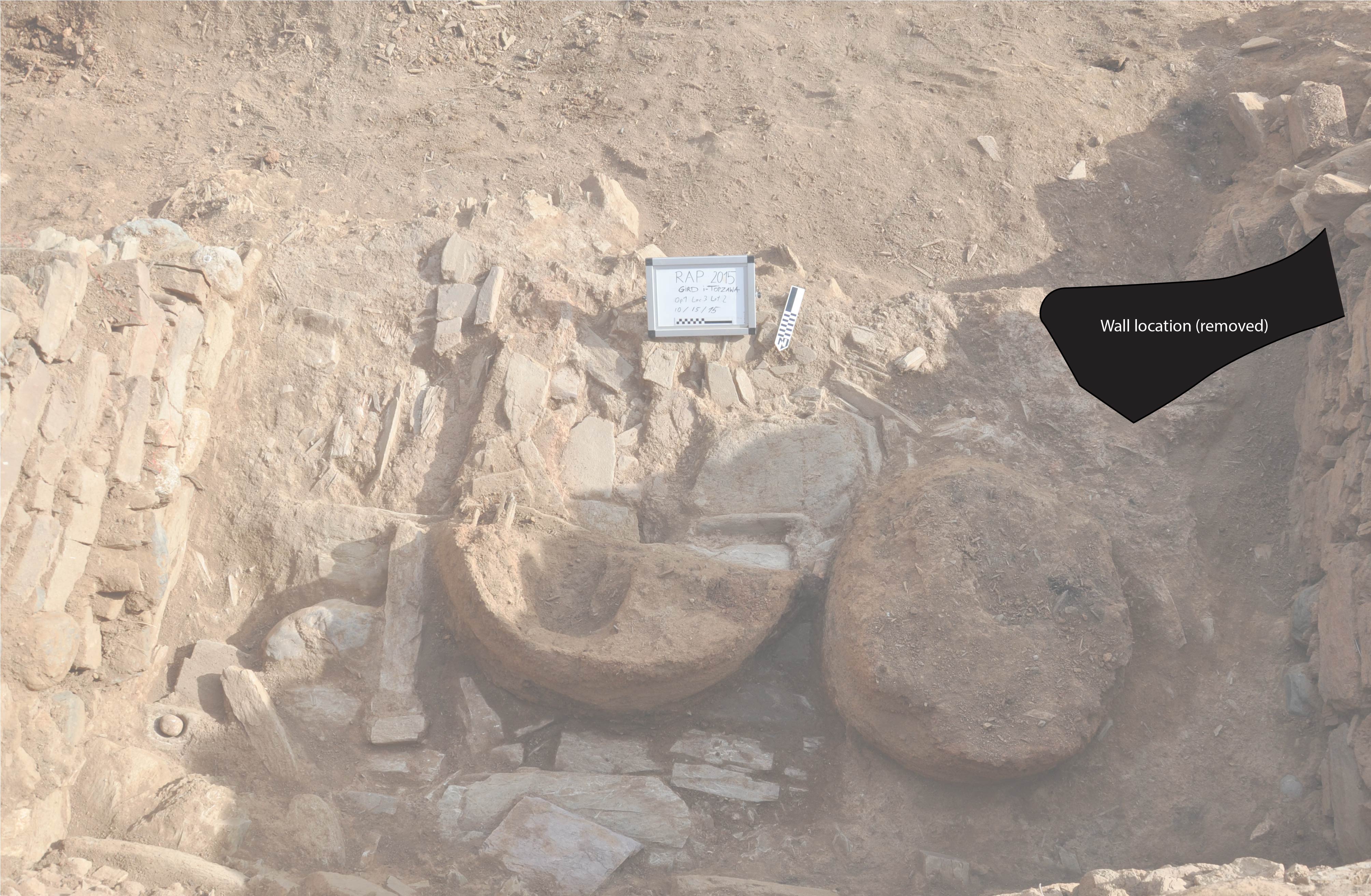
A section of the roadway was left unexcavated between Building 1-W Phase A’s Wall 4 and another series of walls to the east. Given the depth of excavation in this area and the lack of continuity between it and the western trench of Building 1A, the identity of the collection of stones in this area cannot be understood with precision. Describing the excavation here is difficult as well. We uncovered a mass of stones, somewhat aligned at an NW-SE orientation, with additional stones on top in no particular pattern. The stone agglomeration's western face had a flat face, but no corresponding face could be found on the eastern side to indicate it was a wall. The western wall ran up to the outcropping of bedrock below Wall 3.
1C-W
Building 1C, the final use of the building, consisted mainly of a fine Achaemenid burial. While there is some faint evidence that squatters visited the building's destroyed remains and left minimal detritus, the building was not fully reoccupied. The burial was high above the original surface of Building 1B and approximately 20 - 30 cm below the top of Wall 1. While the elevation of the surface at the time of the burial was unknown, the bottom of the burial was only 30 cm or so from the uppermost remnants of the collapsed building below. The team did not note any significant difference in the soil around the body, suggesting that its original position was not far below the surface. For a deep grave, one expects a deep trench with infill that would differ from the surrounding soil. The body lay approximately E-W, in line with the angle of Wall 1, with its head facing west and its feet near the corner of Walls 1 and 3. This positioning, entirely within the upper courses of the remaining wall, suggests that the area’s residents were aware of the structure at the time of the burial.
Our team’s osteoarcheologist did not evaluate the skeleton, but we believed it to be a woman, possibly elderly. While the surrounding moist soil heavily degraded the bones, the articulated skeleton had both arms resting on her chest. The skeleton measured 40.5 cm long from the top of the femur to the feet. The left arm was bent at 90 degrees, resting slightly above the pelvis' top, while the right arm was curled up with the hand near the skull. On the body were several ornate grave goods, including a bracelet, a fibula, ring, earrings, a pin, as well as many beads, discussed in depth in the subsequent Finds section. Directly next to the body were two small jars with narrow necks (Plate 17.2, 17.3), but their rims were, unfortunately, missing, preventing more specific dating or analysis of their characteristics. Overall, the assemblage best corresponds to the Achaemenid Period, most clearly indicated by the fibula. The richness of the grave goods, with ornate metal designs and collections of rare and uncommon stones used to create beads, makes the burial’s location all the more notable. The burial was likely somewhat contemporary to another site excavated by RAP, Ghabrestan-i Topzawa, discussed later in this chapter. That tomb lacked the Gund-i Topzawa burial's fine goods but had a far more elaborate and deliberate tomb construction. It is worth considering how the sites different locations in the Sidekan area and manner of inhumations led to the difference in associated burial goods.
##### Building 1-W Phase B: Reconstruction and Destruction
Before beginning an attempt to reconstruct the layout and use of Building 1B in antiquity, it is worth beginning with a quote from Edmund R. Leach, an ethnographer who visited the Rowanduz area in 1938. He largely followed Hamilton’s newly built road from Shaqlawa up to the town of Rayat, near the Iranian border. His account of the Kurds noted their culture, politics, and economic activities. Notably, he described a typical house in the area in detail. His description of the Kurdish homes of the Rowanduz area is reproduced below, with emphasis added in sections that have particular relevance to Gund-i Topzawa:
The shape is rectangular but there is no consistency in size or plan. As a rule, the main door faces downhill and leads out on to the roof of the house immediately below, but this practice varies. The walls are usually of rough-cut stone set in a mud plaster about two-foot-thick, but the modern tendency is to substitute sun-dried mudbrick for the stone and plaster. Stone houses are two stories high, but this is rather unusual; in such cases the upper story is reached by an outside ladder. All rooms have windows in the outside wall but, except in the Agha’s houses, there are very rarely any shutters. The fire is set in a small floor pit, there is sometimes a proper smoke vent in the roof but more usually the only escape for smoke is through the window. The roof is flat, sloping downwards slightly towards the front, the main roof beams run horizontally, parallel to the hill contours, while over them is laid a thick layer of thin branches about the thickness of peasticks. This is given a top dressing several inches thick of a slurry made from lime, ashes and rubble. In dry weather this sets hard and provides a perfectly rigid floor, but it is not true cement. Under rain, it quickly goes soft and must be kept constantly rolled if leaks are to be avoided… It may be mentioned that the most valuable parts of the house are the roof beams. Straight baulks of timber of adequate length are hard to obtain, and only Aghas can afford anything really substantial. If for any reason a peasant decides to build a new house, he dismantles the roof of his old one and uses the materials for his new house. A village site that has been abandoned thus reverts almost immediately to common scrub (Leach 1940, 49).
This description of a typical Sorani Kurdish house in the 1940s is useful as a reference when reconstructing GT Building 1B, comparing the structures’ similarities and differences. Ethnographies can be helpful signposts for understanding pre-modern structures, but there are certain aspects we expect to change over the millennia. Even across seemingly close distances in the same periods are differences. In Kramer’s ethnography of Aliabad, only a few decades after Leach made his observations, the houses were built primarily of mudbrick on a stone foundation but shared the same tendency to remove the roofing beams when building a new home at a different location (1982, 90–94). Understanding the destruction event and its stratigraphic evidence provides a needed foundational understanding of the standing structure before the conflagration. That knowledge allows a rough estimation of each room's form and function in Gund-i Topzawa Building 1B. The archaeological remnants of features in rooms can often provide clues to their original function, despite residents' insistence of continually altering the primary function (Kramer 1982, 97).
The destruction event that ended Building 1B’s occupation preserved many of the inhabitants' objects and provided insights into the building's upper floor, lost to time. Figure 4.9 displays the parallel west-facing sections of Rooms 2 and 3. The two sections' similar stratigraphic sequences reveal the progression of the building’s destruction. Room 3’s section was preserved to support the partially collapsing Wall 4 and includes upper layers that were removed at the time of Room 2 section’s drawing but was not excavated to the same depth as Room 2. Notably, Room 2’s section covers the portion of the room covering the two eastern pithoi discussed above, resulting in slightly varied stratigraphy than that in Room 3. In addition, Room 2’s south-facing section, depicted in Figure 4.10, provides an alternative angle to the Room 2 stratigraphy in Figure 4.9. Its larger recorded area also reveals how the room’s platform affected the deposition of materials during the destruction event. Table 3 provides the list of stratigraphic layers in the two rooms three sections and their respective matrix consistency. Room 3, absent the complications of stratigraphy caused by Room 2’s platform, is the preferred location to discuss the phases of destruction.

class="w-full max-w-3xl mx-auto border border-white/10 group-hover:border-[var(--color-brand-orange)] transition-all"
loading="lazy" />
Figure 4.9: Gund-i Topzawa Building 1-W Phase B Stratigraphy Comparison, West-Facing Sections
(click to enlarge)
Figure 4.9 not yet available
Figure 4.9: Gund-i Topzawa Building 1-W Phase B Stratigraphy Comparison, West-Facing Sections
Figure 4.10 not yet available
class="w-full max-w-3xl mx-auto border border-white/10 group-hover:border-[var(--color-brand-orange)] transition-all"
loading="lazy" />
Figure 4.10: Room 2 South Facing Section
(click to enlarge)
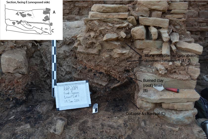
Room 3 (Figure 4.9.R3) was not entirely excavated to the floor level of the building’s destruction. Rather, there was approximately 10 cm between that floor, visible in the north-facing section (not drawn), and the room's exposed limits. Layer 5 in the section drawing, the lowest level, abutted the floor but represented one stratigraphic event after the floor's sealing. Layer 5 had a high proportion of ash and charcoal along with medium-sized building stones. Sloping southwards, the layer was as thick as 40 cm in the northern rear of the room, narrowing to only 10 cm at its southern edge. The bottom of Layer 5 was delimited by a charcoal line, with additional inclusions noted in the section. Layer 4, a compact (5 – 10 cm) yellowish-red layer of baked sandy clay, also sloped downwards to the south. Above, Layer 3’s soil matrix was similar to Layer 5 but lacked the charcoal lenses and contained large to medium-sized stones from the wall collapse. The lower level of Layer 3 sloped downwards with Layer 4, but its top was mostly level. As a result, the northern extent was less than 5 cm thick, while the south was as thick as 50 cm and full of large stone collapse. Layer 2 was a “sealing” phase over the lower levels. The level’s matrix was compact yellow-red clay, surface-like, with a few specs of charcoal inclusions, many small stone chips, and small sherds laying flat or embedded in the layer. Notably, this layer is roughly level, with a drop of less than 5 cm between the north and south of the room. Its flat surface suggests that this material was deposited after the lower destruction material settled. The ceramic sherds would indicate the layer served as a surface for a small or short-lived squatter occupation. The top level of the section, Layer 1, was at least 60 cm thick, consisting of sandy clay with a high proportion of small stone chips and larger stone blocks typical of the surrounding walls.
Table 3: Connection between Layers in Building 1-W Phase B, Rooms 2 and 3
The west-facing section in Room 2 (4.9.R2) parallels Room 3’s section (4.9.R2). While they are not at the same elevation, the shared patterns provide indications of the rooms’ similarities and differences. This section hid the two in situ pithoi from the platform, the knowledge of which explains some of the irregular phases. At the lowest level was Layer 5, the surface of the platform. It was a brown matrix, with small stones mixed, and its top slopes downwards at a moderate angle. Covering the layer was Layer 4, a 30 cm thick, dense matrix of charcoal from burning. It sloped downwards as well, with its southern end coming to a point at a large stone in the section. While the section drawing does not indicate the layer above, Layer 3, was distinct from Layer 1, the difference in matrix consistency, parallel deposition visible in Room 3, later observed irregularities in deposition over the covered pithoi, and the intrusive Layer 2 support the existence of a separate layer. Layer 3 consisted of compact clay, with small stone inclusions as well as small-to-medium charcoal lenses intermixed.
Layer 2 divided layers 1 and 3 in Room 2 (Figure 4.9.R2) and provides the strongest link between the stratigraphic sequences of Rooms 2 and 3. Layer 2 consisted of a reddish-yellow burnt clay, with small stone inclusions embedded in the matrix. Although the preserved portion of Layer 2 in the section appears level, like that of Layer 2 in Room 3 (Figure 4.9.R3), the alternative angle of the section and the building collapse in the layer above suggests that this level equates to Room 3’s Layer 4. The burnt clay in both rooms is likely the fire-hardened mud or “slurry made from lime” that Leach (1940, 49) noted covered the roofs of similar houses. Further, the large charcoal lens depicted in Room 2’s west-facing section (Figure 4.9.R2), at the northern edge of Layer 2, was likely a large roofing beam from the structure, burning hot as the roof’s material congealed. The top portion of the drawn section, Layer 1, consisted of brown sandy clay, with small bits of charcoal intermixed with large stone collapse from the surrounding walls.
Room 2’s south-facing section (Figure 4.10) can help better elucidate the relationship between these layers and the reasons for the lower material's southern slope. The south-facing Room 2 section was drawn at an earlier point in the excavations, but Room 2’s west-facing section (Figure 4.9.R2) corresponds to the east portion of Figure 4.10 that rises approximately 40 cm above the surface to the west. This effectively presents a three-dimensional view of the corner of Room 2. The numbering of the layers in Figure 4.10 equates to the layers in Figure 4.9.R2 despite the different stratigraphic pattern in Room 2’s west. Layer 5, wedged between the collapse above and bedrock below, consisted of a brown soil matrix with moderate inclusions. The two storage pithoi in the room’s northeastern corner rest on this bedrock, which the section reveals is the cause of the dramatically sloped material to the west. Layer 4 was largely charcoal, thick in parts. The alternative perspective shows that the southern slope in Figure 4.9.R2, Layer 4, was actually a sloping southwestern layer, filling the lower levels below the bedrock platform.
Layer 3 was composed of compact clay with small stone inclusions and small to moderately sized charcoal concentrations mixed into the matrix. Layer 2 was the layer of reddish-yellow burnt clay with small stone inclusions, connecting the alternative perspective of Room 2 and Room 3’s Layer 4. Like the lower layers, the level significantly dips as it moves west, contrasting the seemingly level perspective of the west-facing section (Figure 4.9.R2). Layer 1 shows the amount that the levels “fell” to the west with its large stones from the wall collapse tumbling to the lower levels. The layer’s consistency was sandy clay with small to medium-sized charcoal. The combination of stratigraphic perspectives demonstrates the sequence of the building’s collapse, with gravity encouraging a southwest fall into the lowest portions of the building. Given the hillside’s slope and the eastern bedrock outcropping, this may be primarily a result of the surrounding topography.
Combining the multiple angles reconstructs the destruction event in the upper, non-preserved levels of Building 1B (Table 3). Room 3’s Layer 2, the so-called sealing layer, possibly corresponded to the top of the depicted section in Room 2 (not drawn). The hardened clay was likely a result of sun drying rather than desiccation from the fire's residual heat. Layer 3 in Room 3 and Layer 1 in Room 2 was the collapse of the building’s walls relatively soon after the main destruction event, with the small quantity of charcoal indicating that the fire was largely smothered by this collapse. The fire-hardened roof clay of Room 2’s Layer 2 and Room 3’s Layer 4 sloped towards the hillside’s southern slope and covered the bulk of the building’s material. Below the roof, Room 2’s Layer 3 and Room 3’s Layer 5 likely contained the bulk of the material on the building’s probable second story that was covered by the collapsed roof. Regarding a second story, Room 3 does not clearly show evidence of a second story, but given the excavation did not reach the entirety of the floor and the documentation of likely beam emplacements in the wall, a second story likely extended over the entirety of Rooms 2 and 3. Room 3’s Layer 5 was a mixture of compact clay and dense charcoal that was differentiated into two layers in Room 2. The collapse material above the floor, Room 2’s Layer 5, included significant amounts of artifacts, suggesting it was part of the interior of the house before destruction.
Room 1’s stratigraphy, while not depicted easily in a section drawing, consisted of a large charcoal burning layer, sealed by a thin clay layer. The charcoal layer fell directly upon the in situ pithoi below, confirming it originated from the roof or ceiling above Room 1. Unlike Rooms 2 and 3, however, there is no intermediate layer of mixed stone collapse between the charcoal and clay sealing layer. Room 1’s charcoal lies directly adjacent to the clay layer. That suggests that while Room 1 was roofed like the two proximate rooms, it did not have a second story. An interpretation of a single-story roofed spaced here corresponds with the room’s size and somewhat unique shape.
The knowledge of the destruction event and the building’s second story leads to a partial reconstruction of Building 1B’s use and function. Interpreting its use helps elucidate the Iron Age inhabitants' behaviors and provides insights into the density and organization of population in the Topzawa Valley system. The content of each room reveals additional details about the purpose of each space and aids in the overall reconstruction of the building.
Room 1’s overall layout was established above – a triangular room with two or three large pithoi, a fragment of a tannur, the base of a small plaster oven feature, and the box niche at the intersection of Walls 1 and 2. While the tannur and plaster oven indicates cooking in the space, reconstructing the overall use of Room 1 requires discussing the niche’s original purpose and how it relates to the room overall. The niche was likely constructed for one of two possibilities: a chimney or a storage nook.
A chimney presents an intriguing possibility, given the large quantities of charcoal and ash in the room. Most of this burning was caused by the destruction event, but the small southwestern hearth-like feature suggests there was at least some fire in the room during the occupation period. That hearth was far closer to the southern portion of the room, away from the niche. The southern portion of the room was destroyed during the road construction, and thus the existence of any southern wall to enclose the area is in doubt. Additionally, Leach’s description of Rowanduz Kurdish house notes that the rooms did not have chimneys but rather let the smoke exhaust through windows, further eliminating the possibility the feature at Gund-i Topzawa served as a chimney.
The alternative explanation is the simplest – this box was merely a small box to store goods. As noted in the previous section, the excavation did not recover any objects from the niche. However, objects stored in niches like this are unlikely to be items that preserve well in the archaeological record. From ethnographic research, specifically in the Central Zagros of Central Iran, Kramer noted houses with many niches of similar dimensions that stored items like photographs, personal mementos, serving trays, or other everyday items. In many instances, families covered these niches with a decorative cloth hanging, a material that would not preserve in the archaeological record (Kramer 1982, 101). This is the most likely use of this niche by the inhabitants of Building 1-W Phase B. However, the box may not be contemporary with this phase. The excavators noted during clearing out the upper extent of Room 1 that the box may be intrusive to the structure’s walls, raising the possibility it was built by squatters or an addition to the outer wall during the construction of Room 1.
Pulling together information from the stratigraphy, architecture, pottery vessel types, and archaeobotany provides an interpretation of the function of Room 1 at the time of its destruction in the Iron Age. Room 1 contained at least two storage pithoi, a hearth feature in the room’s south, a moderate amount of cereal grains, a large number of grape seeds or skins, and was roofed likely with some combination of wood, branches, mud, and various flora. The vessels recovered in the room are disproportionately from bowls. Together, it appears the purpose of this room was multi-functional – a location in the lower level of the building for cooking and storing foodstuffs. Most of the space was reserved for storage or cooking activities. The absence of a second story removes the possibility that these bowls fell with collapse from an upper story reserved for eating and drinking. Further evidence of this space as a joint storage and cooking space is a single lid (Plate 43.1), likely for cooking.
The primary feature of Room 2 was the large bedrock platform with its two clay features of uncertain function and two pithoi. Initially, the team believed these features to be ovens primarily due to their size and the thick clay walls. A more likely interpretation, however, is as storage bins. Carol Kramer’s ethnographic research of the pseudonymous site of “Aliabad” in 1975 provides invaluable data on home construction and utilization and includes a description of the various storage methodologies, including clay bins (Kramer 1982). Aliabad was a town of approximately 400 residents located somewhere in the piedmont of the Zagros Mountains of Iran, at an unknown location in either the Hamadan or Kermanshah provinces (Kramer 1982, 10). Although these houses were located in a slightly different environment and constructed primarily of mudbrick, as opposed to stone, the rooms' function was comparable.
Storage bins in the houses of Aliabad were essential features of the structures, vital for keeping agricultural stores dry and safe during long and brutal winters. Many houses had storerooms with the exclusive purpose of long-term agricultural storage and would often block the door for years at a time to protect the stored food (Kramer 1982, 105). In many of these residential complexes, separate storage buildings contained these storerooms. Grain storage was in either deep holes (~1.5m), covered with clay or a lid, or in clay bins that residents filled with flour in September, at the end of the harvesting season (Kramer 1982, 33). The residents constructed bins in a few different methods: as large cylindrical chineh (packed mud), with small feet; cylinders propped up with a cluster of small stones; or cubic shaped boxes. Their tops were either open with a wooden board covering or enclosed by a clay “plug” (Kramer 1982:100). They used their bins for 5 – 20 years before being replaced or rebuilt. In most cases, the bins’ base had a small hole to access the contents.
Room 2’s two clay features most closely resemble the appearance and function of flour or grain storage bins, given their material, positioning, and room location. For one, the hardened clay construction of the bins was ideally suited for dry material storage. The clay features at Gund-i Topzawa were seemingly dried in situ with possible additional hardening during the fire that destroyed the structure. With force applied, the clay quickly crumbled. This type of packed and dried clay is similar to what Kramer observed in the bins of Aliabad. In addition, the thick unfired clay features in Room 2 had few other possible uses. Its solubility prevents any liquid storage or liquid production, like wine pressing. An oven is theoretically possible with this clay material, but multiple factors refute that use. The size of the features would be uncommonly large for ovens, a close examination of the bin’s section suggests the original feature had no top, and the charcoal in the floor and center of the bins resembles the detritus from collapse rather than multiple subsequent cooking events.
Secondly, the bins’ position on top of the stone platform was well suited for storage bins. Separating the bottom of the bins from soil, either using small feet or a stone base, was an important detail observed by Kramer, as penetration by moisture or burrowing animals was calamitous for food storage (Kramer 1982, 33). With the mass of uninterrupted stone directly below and surrounding the bins, the stone guarded against fossorial fauna or soil seepage. Third, the bins’ higher elevation above the occupation floor of Room 2 would be well suited for access from below, perhaps through a small hole in the bins described by Kramer. Other chineh from Aliabad were open on their top with a wooden cover to protect against the elements (Kramer 1982, 34). Our excavations did not observe a hole in the sides of either bin, and given the clay features had no preserved top as seen in the section, wood or a similar covering would be a likely tool to enclose and access the interior. As noted above, the sectioned bin’s preserved wall height was between 26 – 40 cm and it measured approximately 1 m in diameter. An estimate of the preserved portion volume was approximately 142 liters, and its twin feature was roughly the same size, combining to store a significant amount of goods. The bins were likely taller when originally in use, with fragments of the wall in the bins’ interior suggesting additional height. The interpretation of these features as storage bins helps provide an integral datapoint in the reconstruction of Gund-i Topzawa and understanding of the Sidekan Valley – the projected food storage capacity of the building.
Adding to the evidence that these clay features were storage bins were the two (possibly three) pithoi positioned on the stone platform's eastern end. Their semi-permanent placement within stones, propped up, suggests a storage use, with the entirety of the platform serving as a storage area. Apart from the existence of permanent or semi-permanent storage vessels in the area, the platform's elevation compared to the surface below creates an easily accessible area to obtain goods. Thus, the primary purpose of the whole room was likely as storage. The remaining floor was not preserved enough to the south to give any clear clues to its use, apart from a walking surface associated with Doorway 1. While Room 2 possibly contained a cooking feature like that in Room 1, no evidence was preserved further to the south.
On the other side of the doorway, Room 3’s use is far less clear. This obfuscation results from the lack of floor clearing and in part, a result of the absence of architectural or semi-permanent features uncovered during excavation. Interpretation of this room’s function is primarily driven by the destruction, types of pottery vessels, and objects associated with the northwestern fire feature. The possible hearth in the northwest corner of the room could provide clues, but the available evidence provides some assistance in understanding this feature. The evidence for terming this a hearth comes, in part, from the two andirons and single terracotta stand. The word andiron is derived from the iron supports used to hold up fire logs, but the andirons of antiquity, perhaps better termed “fire stands,” more often served to hold pots above the fire (Rahmstorf 2010, 273). Even as rudimentary construction, fire stands would be key components of a hearth.
The tall, legged stand was a roughly circular cylinder of fired clay with a slightly convex bottom and a clubbed top with four small prongs (Figure 4.11.1). It was 16 cm tall with a diameter of 6 cm at its widest extent. Nearby the findspot for the stand were the two andirons. One andiron (Figure 4.11.2) was fully intact, while the other was broken into two pieces. The intact andiron had two horn-like protrusions on each end, with a dip in the middle and a flat base (Figure 4.11.2). It was 16.5 cm long, 8 cm tall, and its “horns” were about 7 cm wide. One side of the andiron also had four parallel impressions in the clay, believed to be part of a handprint. Andirons often fall into two main types, horn-like projections or horseshoe-shaped (Smogorzewska 2004, 152). Despite the peaked “horns” of this andiron, its overall structure resembles a horseshoe. The other andiron was split down its middle, with only one of the presumably two peaked horns remaining. These two andirons, with their parallel dips, would likely support a pot with a fire below. The stand’s use in relation to the fireplace is unclear. Even with its small prongs, its top's limited surface area would serve as inadequate support for any pot wider than a few cm. The stand may have been supported by additional tools unpreserved in the archaeological record or unrecovered during the excavation. The collection of objects does suggest the existence of a hearth in this corner.
The distribution of vessel types in the room had an abnormally high percentage of holemouth jars. Room 1 and Room 2 had 22.22% and 27.88% of their diagnostic sherd assemblage from holemouth jars, while Room 3 almost doubles that proportion, with 52.17%. Further, when attempting to segment the pottery from the upper (Layers 1-2) and lower stories (Layers 2-5), the prevalence of holemouth jars in Room 3 is even more pronounced. In the upper phases, holemouth jars make up 37% of the total, more in line with Rooms 1 and 2’s proportion. In the lower phases, the best representation of the material from Room 3’s final occupation, the percentage of holemouth jars in the diagnostic sherds is 62%. In addition, several sherds from these phases are unidentifiable but have characteristics that may originate from holemouth jars. The holemouth pots range from moderately sized, around 15 to 20 cm, to a few large samples with diameters 50 cm or greater.
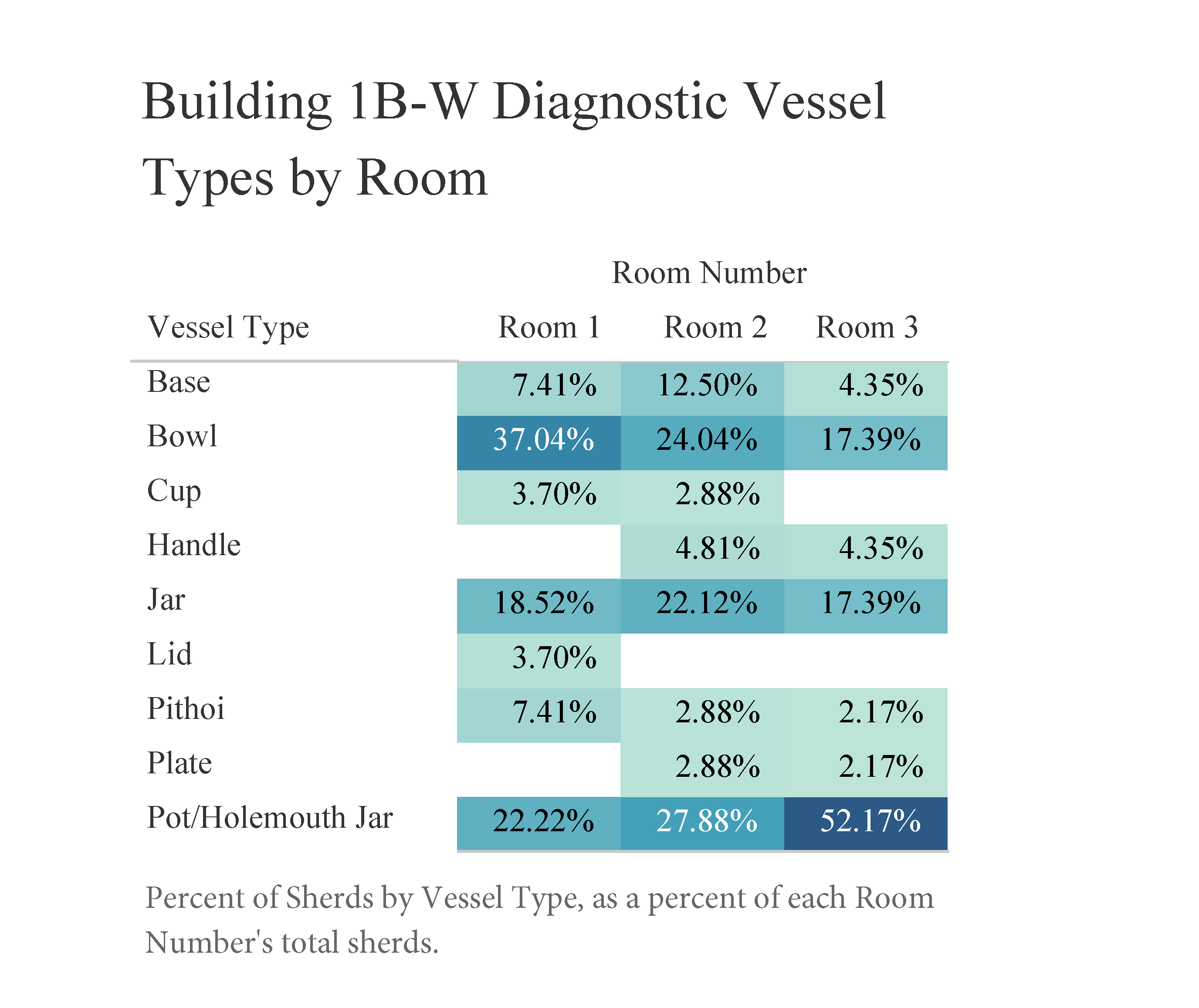
class="w-full max-w-3xl mx-auto border border-white/10 group-hover:border-[var(--color-brand-orange)] transition-all"
loading="lazy" />
Figure 4.11: Gund-i Topzawa Building 1-W Phase B, Room 3 Objects
(click to enlarge)
Holemouth jars are often associated with domestic activities, such as cooking or storage, depending on their size and fabric (Danti 2013; Frank 2019, 93). Cooking vessels have a distinctive ware, typically thick and coarse to stand up to high heat, while many storage holemouth jars maintain a small enough rim diameter to hold in their contents. Room 3’s holemouth jars mostly lack the distinct cooking ware type, but most share the coarse characteristic of cooking ware. Comparable vessel forms (see: Danti 2013 – HM 2a) are used as storage. There was little direct evidence these holemouth jars were used primarily as cooking vessels except for the probable hearth nearby. Kramer notes that in the houses of Aliabad, the residents often blocked off their storeroom doors with stone or clay (Kramer 1982, 106). Doorway 1, while it was not blocked off during the destruction event, could have served as that barricade if the residents of Gund-i Topzawa exhibited similar behavior to the Aliabad residents. Even if some of the jars were used for cooking, there is little chance the entire assemblage served that function. Alternatively, Room 3 may have served as a domestic processing location in addition to storage. Richard Zettler proposed the small stub of Wall 6 in Room 3 surrounded a small area for larding (Personal Communication). While I interpret the wall as a structural feature, if it served as a space for larding or similar activities, the numerous holemouth jars would be used to store the processed output.
Unfortunately, even with the improved stratigraphic control in Room 3, pottery distribution in the upper phases does little to provide clues to the types of activities in the upper story. However, ethnographies show reasonably consistently that rooms in the upper stories were used primarily as living rooms. Leach’s description aligns with that, and Kramer notes that when there is a single room in the second story, that room is always used as a living room (1940; 1982). If there were multiple rooms, secondary rooms often served as storage for lighter goods, Watson dubbing these as “utility rooms” (Watson 1979). The space above Room 3 may have served as a utility room or a living room. Regardless, the second story, spanning Rooms 2 and 3, undoubtedly served as the main occupation space, with additional space for sleeping on the building’s roof.
Buildings 1-E & 2-E: Architecture & Stratigraphy
At the eastern edge of Gund-i Topzawa were two buildings, briefly excavated by our team – Buildings 1-E and 2-E. While neither building was excavated sufficiently to understand the stratigraphy in detail, carbon samples from the 2013 section cleaning and 2014 excavation establish these buildings as predating Building 1-W Phase B. We uncovered scant information about the buildings’ arrangement and contents during excavation – the most pertinent data for the overall understanding of the site were the carbon dates. While they are discussed as two separate buildings, their exact relationship is unclear.
Figure 4.12 not yet available
Figure 4.12 not yet available
Building 1-E’s excavated area includes Wall 1 – its northern wall cut into the hillside like Building 1-W Phase B’s Wall 1 – Wall 2 in the west, and a mostly open space bounded by those walls. Of particular interest was Space 1, a sizeable enclosed alcove built into Wall 1. Walls 1 and 2 used the same construction methods as Building 1-W Phase B, alternating between large horizontal slabs and small perpendicular pieces on each level. Wall 1 ran about 4 m from its western connection at Wall 2 to the limits of the excavation in the east, where the earth mover’s damage knocked the remnants of the wall away. We did not determine Wall 1’s width, but clearing the upper section revealed a portion of another wall back to the north, showing a rebuild or second level resting on the wall. The height from the surface to the top of Wall 1, where the additional wall rests, was about 70 cm. Wall 2 ran up against Wall 1 but did not appear to join. It was approximately 70 cm wide, and its southern extent was cut and destroyed by the road construction to the south.
Figure 4.13 not yet available
Figure 4.13 not yet available
Space 1, ambiguously named to prevent bias regarding its uncertain use, had an opening facing south. Its opening was constructed with a flat door jamb-like stone threshold, two large slabs angled slightly inwards, and a slab on its top, spanning the vertical supports. This entrance was small, roughly 50 cm by 50 cm, but allowed excavators to enter the space. Its interior construction differed significantly from the rest of the construction at Gund-i Topzawa. Instead of long, horizontally laid stones, the interior space was constructed with roughly equal-sized rectangular stone blocks, stepped inwards slightly, and roofed by large stone slabs (Figure 4.13). While we could not excavate all of the soil in the space, we established its height was less than 1 m at its deepest point and about 1 m long from its entrance to the back wall. The cleared soil consisted of a water laid matrix with stones collapsed and mixed in with the material. From the front, large stone slabs, possibly bedrock fragments, sloped downwards to the north. The upper section of the eastern wall of Space 1 contained a small niche, approximately 40 cm tall, wide, and long. The team postulated this niche served as a spot to place a lamp or other portable goods, but there were no remains in this space. Space 1’s interior debris was limited. We recovered one pierced ceramic disc, small amounts of charcoal, and intermittent animal bones. The two archaeobotanical samples from this space did not contain any organic material.
Figure 4.14 not yet available
Figure 4.14 not yet available
The main open space of Building 1-E contained some level pavement stones, a small tannur, ash, and minimal stone collapse. Except for the E-S pavement stone that formed Space 1’s entrance, three other large pavement stones survived the destruction of the road construction. Although the area immediately in front of Space 1 was destroyed, the eastern limit of the entrance aligned with three stones, believed to be the remnants of a threshold given its orientation and flat top in alignment with the rest of the room’s surface. East of the threshold was a tannur 44 cm in diameter. Unlike the fragments of tannur walls and the bins in Building 1-W Phase B, Building 1-E’s tannur exhibits the ovens' distinctive pattern. While only preserved a few centimeters above the surface, its border was a red, hardened-clay, ceramic-like ring coated with charcoal around the inner edges. At the base of the tannur was plaster. The interior of the tannur contained three body sherds but nothing else of note. Immediately to the east of the tannur was a small ash lens lying at the road cut line. Its limited size and depth likely indicate it was the location of some burning activity, probably related to the tannur oven. The area’s surface consisted of brownish-gray compact dirt with red clay and pebble inclusions. Sealing the surface was 3 cm of red clay with large stone collapse embedded in the clay and the surface below. A find of note in this space was a door socket with large and small pivot holes. Its location did not correspond to a conspicuous door location. Unlike Building 1-W Phase B (and similar to the known exposure of 1-W Phase A), Building 1E did not have the distinct charcoal layers running across the surface and collapse indicative of a mass destruction event. The carbon sample from Building 1-E originated from the west of the room and was one of the small charcoal flakes dispersed across the area.
While the open space and the existence of a tannur suggests this area was a courtyard, returning to Leach and Watson's ethnographies inform us that tannurs were more likely than not in the rooms themselves. Further, courtyards were commonly ringed by the rooms of the house. In this instance, Wall 1 could not realistically hold another room to the north, as its primary extent was built into the hillside itself. Thus, this space was likely an interior room. Its surface, reinforced with embedded pebbles, was standard paving for domestic spaces. Unlike Building 1-W Phase B, Building 1-E’s residents had adequate time to clear their valuables and portable goods before complete abandonment. Their slower desertion also sheds light on the identity of Space 1. The most likely interpretation of this stone-built nook was storage. The lack of archaeobotanical remains is explained simply by the lack of conflagration that often preserves organic material. In the enclosed space's moist soil, any agricultural stores would decay long before our excavators entered the space.
Given the weakness of Wall 2, we left an unexcavated balk in the northwestern corner of the room, obscuring the exact relationship between the two walls. Wall 1 appeared to continue past Wall 2, forming another space's rear wall, then connecting to Building 2-E. On the western side of Wall 2, at the corner between Walls 2 and 1 and mostly obscured by the remaining balk, was a small gap in Wall 1, similar to Space 1’s opening. While unable to fully clear and investigate the interior of the space, the space was comparable to the structure of Space 1. The space to the west of Wall 2 had no features of note. We cleaned out its contents to the western room's surface level, but the stone rubble continued past that point. The depth of this space remains unknown. The width of the space between Wall 2 and Building 2-E was approximately 1.5 m.
Building 2-E was poorly defined, but it seems to share Wall 1 with Building 1-E. That wall runs behind Wall 2, behind the intermediate space, and against the western wall of Building 2-E. We did not clear enough rubble in front of the back, northern wall of Building 2-E to confirm the wall’s existence there, however. The western limit of Building 2-E was a well-built wall, in the same style observed across Gund-i Topzawa, about 50 cm wide. From the road cut section, its foundation appeared to rest on bedrock, like the walls in Building 1-W Phase B. About 1.5 m of its height remained, but the upper limit was partially obscured. The only room of Building 2-E was 2.4 m wide. In the south, running E-W along the construction cut line, were the lower remnants of a small wall, only one or two courses wide. While most of the wall was destroyed, it delimits the room's depth as approximately 1.5 m. We did not reach this room’s surface, but there was significant stone collapse, a small number of sherds, and no charcoal burn layer like Building 1-W Phase B. The building’s interpretation is primarily based on the radiocarbon sample that provides an Iron I dating, as the dearth ceramic assemblage offers few clues to either the periodization of use of the building
Radiocarbon Dating
While the excavation recovered and subsequently tested radiocarbon samples from Buildings 1-W Phase B, 1-E, and 2-E, three factors complicate dating Gund-i Topzawa Building 1-W Phase B: radiocarbon dating calibration, the Halstatt Plateau, and the old wood problem. The first problem is shared by all archaeological excavations, the calibration of the date. The basic principle of radiocarbon dating (i.e., 14C Dating) is 14C, the inert radioactive carbon molecule, is continuously created through the bombardment of nitrogen by solar rays and eventually becomes 14CO2, carbon dioxide. That gas is subsequently absorbed by plants through photosynthesis, providing the building block for all living things. Once the plant dies and ceases absorbing new carbon, the remaining carbon decays, losing electrons at a known rate, with a quantifiable metric for its half-life. Based on Libby’s Nobel Prize winning research, the mean accepted half-life is 5,568 years, using the carbon in the atmosphere in 1950 CE as a starting point (Libby 1955). Detecting the proportion of radiocarbon in the sample and utilizing those metrics returns a date before the present. That is the radiocarbon age estimate, x, expressed as before present (BP), along with the laboratory error, σ, expressed as x ± σ (Buck and Juarez 2017). However, the BP determination does not return the real calendar date because, in part, the inaccuracies of Libby’s half-life decay time, but more significantly, the proportion of radiocarbon in the atmosphere varies over time (de Vries 1958; Brock Ramsey 2017).
Using yearly tree rings and analyzing the proportion of radiocarbon in each year’s tree ring, scientists constructed a calibration curve with each year’s radiocarbon proportion dating back 55,000 years. Each tree ring represents one year, and as the subsequent year’s ring grows, the previous ring stops absorbing carbon. Because the climatic events influence tree rings' thickness, dendrochronologists can match the rings of different trees, creating a continuous sequence across thousands of trees. Subsequent and more accurate radiocarbon calibration curves have been published as the dataset increases and improves. The accepted calibration curve for use in the Northern Hemisphere is IntCal, which began as far back as IntCal98, in 1998, up to the most recent IntCal20 (Stuiver et al. 1998; Reimer and et al. 2013; Reimer 2020). Notably, for archaeological analysis purposes, 14 cal ca BP, i.e., the Holocene, relies entirely on dendrochronology and will be less susceptible to changes with subsequent IntCal publications (Törnqvist et al. 2015). Even with the recent IntCal20 publication, calibrated dates from Gund-i Topzawa changed by less than a decade. Inputting the raw radiocarbon dates, expressed as years BP, into the calibration curve, usually done using software like OxCal, returns a date range (Bronk Ramsey 1995; 2009). Given the precision and irregularity of the calibration curve and the laboratory error from the radiocarbon’s BP determination, this returns a probabilistic output of dates. The regular bell-shaped distribution of BP dates mapped alongside the irregular radiocarbon calibration curve creates statistical probabilities of specific date ranges (Plicht and Mook 1987). The calibrated calendar date can return a narrow range for periods when the calibration curve demonstrates a regular, continuous, and steep slope. Issues arise, however, when the calibration curve flattens or exhibits irregular decay.
The second complication is the Hallstatt Plateau, a multi-century plateau in the calibration curve that makes radiocarbon dating a narrow date range nearly impossible. The curve stretches from approximately 750 BCE to 400 BCE and takes its name from the site of Hallstatt in the Austrian alps that initially helped establish the relative and absolute chronology of Iron Age Europe (James 1993; Friedrich and Hennig 1996; Nijboer et al. 2000). Even with high laboratory precision, the implication is a single date often returns a date range of multiple centuries. Under one standard deviation (i.e., “sigma,” equaling 68%), the calibrated dates can easily span two centuries. Adding the additional rigor of two standard deviations (two sigmas, 95.4%) increases the range up to 350 years. By contrast, a slightly earlier date that avoids the Hallstatt Plateau, in the range of 800 – 900 BCE, can return a range of 150 years at a 95.4% confidence interval. One method used to provide more narrow calibrated dates is the so-called “wiggle-match method,” which uses radiocarbon dates from known stratigraphic or dendrochronological sequences to improve the precision of the calibration (Ferguson, Huber, and Suess 1966; Jacobsson et al. 2018). While the method can improve calibration, even with as many as 50 consecutive tree rings, the resulting calibrated dates are still less accurate than periods surrounding the Hallstatt plateau. Further, the lack of stratigraphic chronological differences at Gund-i Topzawa makes that method impossible.
The final issue of radiocarbon calibration at Gund-i Topzawa is shared by many excavations – the “old wood problem” of large structural beams. As the absorption of new 14C ceases when a living organism dies, when a tree is cut down, the 14C in the plant is fixed to that point (Waterbolk 1971; Schiffer 1986; Kim et al. 2019). For short-lived plants, like seeds associated with food intended for immediate or seasonal consumption, this date often accurately reflects the surrounding material's date (Nolan 2012; Huckleberry and Rittenour 2014). However, substantial structural wood, such as roofing beams, was reused over decades or centuries – Leach’s ethnographic account of Kurdish houses demonstrates this pattern continuing into at least the 19th century.
Radiocarbon dating is fundamentally dating non-cultural events, like the growth of tree rings and the death of cells, and archaeologists must interpret these events in the framework of the surrounding cultural activities (Dean 1978). Wood is often the only material preserved well enough for radiocarbon sampling, despite its inherent problems as a proxy for the age of human activity. Further, given the large diameter of many structural beams, the charcoal from a tree may not even include the most recent growth ring, returning an even earlier date. This old wood problem complicates the dating of destroyed buildings when the roofing charcoal is intermixed with charcoal from more secure, time-limited contexts like ovens. However, in specific periods or areas of the world, the old wood effect is less pronounced or does not exist at all. Smaller, less durable wooden beams utilized over a shorter period or the ecological conditions that accelerate the decay of wooden materials can negate much of the bias from the effect (Kim et al. 2019). Unfortunately, northeastern Iraq does not have the moist environment that accelerates wood decay and leads to shorter utilized wood beams. In most cases, charcoal wood dating on its own can provide the terminus post quem for a building, as a building could not be built before the cessation of 14C absorption in the wood.
Table 4: Calibrated GT Building 1-W Phase B Dates
While the carbon samples from GT Building 1-W Phase B have some stratigraphic distinction between the upper and lower excavation levels, analysis shows that these layers are part of the same destruction event. That prevents using radiocarbon techniques like the wiggle method or Bayesian analysis. Fortunately, the number of carbon samples from Building 1B-W, three of which were seeds, allow further refinement of the broad calibrated date ranges seen in Table 2. All samples were run at the University of Arizona’s AMS Lab and are calibrated using OxCal 4.4 (Bronk Ramsey 2009). Observing the calibrated dates in Table 2, apart from the two samples with relatively narrow date ranges (649, 1123) in the early 8th century, most of the dates span the centuries flagged as problematic with the Hallstatt Plateau. Observing the probabilistic plot of the dates (Figure 4.15) shows that sample 505 has a similar distribution to 649 and 1123, with a slightly elevated probability of originating post-8th century. Notably, 1123 and 1149 originate from the same context – the interior of the pithoi in the northeast corner of Room 2 – and are both seeds. Thus they should date to about the same year, despite 1149’s much wider date distribution. The remaining samples’ date ranges, however, extend over multiple centuries. One method for further refining the date of the building is the tau method.
Figure 4.15 not yet available
Figure 4.15 not yet available
The basic principle underlying the tau method is events are arranged in an order assumed to be exponentially distributed, rising to a maximum event probability at the end event (OxCal 4.4; Garfinkel et al. 2012). As the destruction event at Gund-i Topzawa Building 1-W Phase B presumably caused the carbonization of wood and seeds at the site, the seed samples are most likely the remnants from the structure's final days. Using that framework, the latter dates of the wood samples are decreased in probability. Running the tau provides a beginning range, “T,” from 853 – 592 BCE, and an ending range, “E,” from 762 – 521 BCE. As those dates do not provide any further clarity or specificity, breaking down the modeled dates can help determine a likely range for the destruction event at Gund-i Topzawa. Viewing the multi-plot of the modeled dates (Figure 4.16) shows the probabilities’ concentration around the first half of the 8th century. Comparing 1123 and 1149 are particularly instructive. If we model them as a single sample (erroneously), there is a 68% probability the date falls between 800 – 750 BCE, versus the 68% probability of falling between 798 – 772 BCE for sample 1123 alone. With the tau model, sample 1149 has a 52.5% chance of falling between 789 – 716 BCE. Despite the probability of a later date, the cluster of calibrated and modeled dates clusters around the first half of the 8th century. This period corresponds to the cultural material. The excavations at Mudjesir returned a date in the 9th century, and the pottery surrounding that radiocarbon date matches the Gund-i Topzawa assemblage (Danti and Ashby Forthcoming). One consequence of an early 8th-century destruction date at Gund-i Topzawa Building 1-W Phase B is it removes the possibility that Sargon II destroyed this structure during his attack on Muṣaṣir. Based on radiocarbon probabilities, the chance of a 714 BCE destruction is less likely than a destruction date in the 5th century.
Figure 4.16 not yet available
Figure 4.16 not yet available
The remaining radiocarbon samples from Gund-i Topzawa are far simpler to discuss as there are only three, and their BP determination avoids the additional complication caused by the Hallstatt plateau. Building 1-E’s single excavated radiocarbon sample, from east of Wall 2, returned a calibrated date of 1261 – 1107 BCE, with a 90.2% probability (OxCal 4.4, Bronk Ramsey 2009, Reimer 2020). Two of the samples collected during the 2013 section cleaning seemingly originate from Buildings 1-E and 2-E, based on their positioning between exposed walls (Figure 4.1). Sample 455 may originate from the partially excavated space between Buildings 1-E and 2-E, given the walls’ close location. Its date returns a two-sigma range of 1191 – 903 BCE, but with a 93.1% probability of falling between 1128 and 903 BCE. The other sample from 2013, 453, had a calibrated two-sigma date of 996 – 814 BCE. The incongruity of the two samples related to Building 1-E may be caused by one of two reasons. One, the matching up of the 2013 sample to the 2014 excavation location was incorrect either because of a recording error in 2013 or a fault in matching shared landmarks. Alternatively, the two samples relate to the same building but are from two separate occupation phases. Given the two probability curves are effectively sequential, there is a possibility of subsequent occupation levels. The upper wall, resting on Wall 1 in Building 1-E, may have been part of a later occupation and the source of the later radiocarbon date. Despite the open questions about the radiocarbon dates from Gund-i Topzawa East, they are all earlier than the occupation at 1-W Phase B, possibly contemporary with the occupation of 1-W Phase A.
Table 5: Non-Building 1-W Phase B Gund-i Topzawa Dates
Finds
The finds from Gund-i Topzawa fall into two categories: the fine goods associated with the burial in 1-W Phase A and the more common goods found mainly in 1-W Phase B. Objects from Gund-i Topzawa 1-W Phase B tend to be associated with domestic activities like weaving and food processing. There was some degree of differentiation of objects between rooms, though the rooms’ overlapping object types and somewhat ambiguous use are not sufficient to use the objects as explicit proxies of room purpose.
All Room 1’s objects, three clay discs, were seemingly associated with weaving production. One was pierced through the middle (1079), one was in the process of being pierced with two parallel holes partially perforating (Figure 4.17), and one was simply a clay rounded disc (1078). The rounded discs are unextraordinary, but the perforation in two suggests an association with weaving. One of the simplest types of loom weights, perforated discs, served to anchor wool threads in weighted looms (Nelson 2016). In some instances, a “perforated roundel” made from discarded ceramic sherds can also serve as spindle whorls, although Yener believes these discs are more likely loom weights (Yener 1990, 403; Keith 1998, 505–7). Spindle whorls are often hard to distinguish from beads, as they are ubiquitous and have similar forms. However, spindle whorls are differentiated in two main characteristics. Spindle whorls are almost always larger than beads but usually under 40 mm in diameter, and they have larger central perforations than those in beads to allow for the thicker wool to pass through (Liu 1978, 90–91). All three discs from Room 1 range from 3 to 5 cm in diameter; thus, their size alone would likely preclude use as spindle whorls. However, while Room 1 did not contain likely spindle whorls, Rooms 2 and 3 had likely examples.
Figure 4.17 not yet available
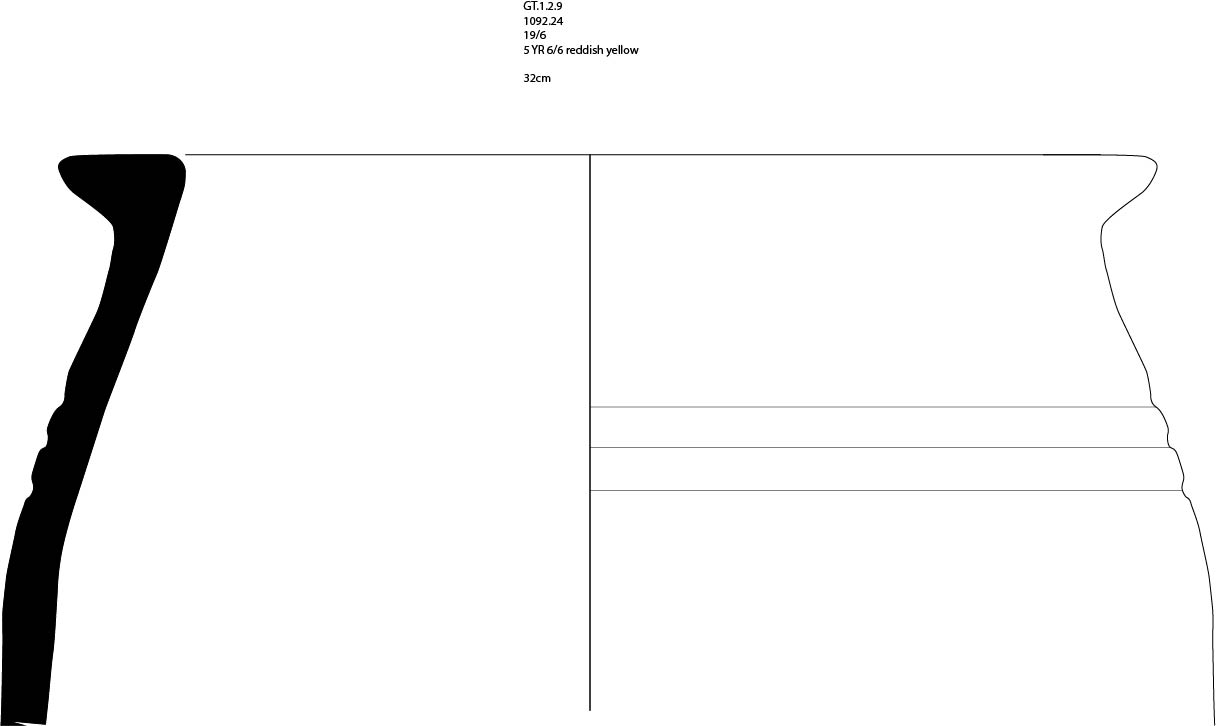
class="w-full max-w-3xl mx-auto border border-white/10 group-hover:border-[var(--color-brand-orange)] transition-all"
loading="lazy" />
Figure 4.17: Partially Pierced Disc, GT Building 1-W Phase B Room 1
(click to enlarge)
Rooms 2 and 3 contained small spindle whorls made of bone. While spindle whorls were most often made of stone, metal, or clay, bone was a moderately common material (Liu 1978, 92; Kimbrough 2006, 57). Room 2’s spindle whorl (Figure 4.18.2), while partially broken, had a characteristic convex top pierced through its center. Its diameter was approximately 4 cm, and its shape was nearly identical to other bone spindle whorls at Bastam (Kroll 1979, figs. 15, 7). The shape and material alone do not provide much chronological assistance, as one of the two Bastam examples dates to the medieval phase and another to the Urartian period. The bone spindle whorl in Room 3 (Figure 4.19.2) had the same shape but slightly smaller at 3 cm. Neither spindle whorl was directly associated with other weaving tools. Room 2 also contained another pierced ceramic disc (Figure 4.18.3), with a darker and harder ware than those in Room 1.
Figure 4.18 not yet available
Figure 4.18 not yet available
In addition, there was another disc, unpierced and made of limestone (Figure 4.18.4). Despite its similarity to the clay discs, its unpierced center and finer material does not suggest it functioned as a loom weight. Both discs originated from an upper context, likely material from the second floor of the building. In the detritus that collapsed over the rear pithoi in Room 2 was a large stone (1140), 10 by 12 cm, with a well-drilled hole about 2.5 cm in diameter. The stone was likely a weight of some type, possibly a loom weight. Room 3 also contained a larger stone with slight hole indentations that may have also been intended as a weight.
While there was a relative paucity of weaving-related artifacts, they support the hypothesis that Building 1-W Phase B was a domestic, multi-functional space. The low quality of the whorls corresponds to local production. Even the size of the whorls is indicative of the type of weaving activity. Whorls’ weights are associated with weaving different types of wool. Whorls over 150 grams are used for a coarse thread, while whorls under 8 grams are used to create a fine thread from short-staple wool (Barber 1991, 52). If Gund-i Topzawa was a settlement in the hinterlands, near sheep grazing, the inhabitants would likely be transforming the raw wool into a coarse material.
Figure 4.19 not yet available
Figure 4.19 not yet available
Along with finds associated with weaving, there were a handful of objects related to food processing. The direct examples were two pestles in Room 2 and a third in Room 3. One (Figure 4.18.1) in Room 2 was clearly identifiable as a pestle, with an enlarged and rounded top, narrowing to a smaller diameter further down the base. Its counterparts (1312, 770) lacked customization and refinement. Those stones were simply rounded at the top. Notably, the pestles’ stone was not the same variety found in the surrounding walls and across Gund-i Topzawa. While unable to examine the stones in detail, they appear to be a much harder stone than the shale in the Topzawa Valley, likely some type of igneous rock like granite. Building 1-W Phase B held no identifiable mortars. Room 3 contained a strange, worked stone with angled markings, possibly created by rope friction, and a depression possibly caused by repetitive friction from the nearby pestle. If repetitive rope motions caused the markings on the rear of the stone, that action's reasons are unclear.
Table 6: Gund-i Topzawa Building 1-W Phase B Finds
Two blades, located in the upper collapse of Room 2, have a possible association with food processing. One blade (Figure 4.18.6) retained its tip and 10 cm of its body, while the other blade’s (Figure 4.18.5) point was destroyed. The blades’ widths and structures ensure they did not originally belong to the same tool. Similar blades were recovered from Urartian sites (Lehmann-Haupt 1931, 545–47; Kroll 1979, 158). The blade’s distinct shape, with one side of the blade highly curved and its opposite nearly straight, is characteristic of sickles. These blades are often found in contexts along with other agricultural instruments (Çifçi 2017, 50). While none of the other tools, like pitchforks or plows, were found at Gund-i Topzawa, wooden versions would not have survived the destruction or post-depositional processes. These sickles, along with the pestles and archaeobotanical samples, support the hypothesis that Gund-i Topzawa Building 1-W Phase B was a domestic homestead, intimately connected with the agriculture in the surrounding valley.
One object from 1-W Phase B stands out as not part of a purely domestic assemblage for the production of goods – a spearhead. The spearhead (Figure 4.20) was 22 cm long and 3 cm wide, with its socket 2 cm in diameter. It was constructed of iron and heavily corroded, obscuring any fine details on the blade apart from a slightly raised spine. Its findspot was notable – the team recovered the spearhead, laying flat, in the lowest levels of Room 2 as part of an early morning cleaning context. None of the surrounding objects had any relation to the spear. While there is no reason to eliminate it from this study, its location directly adjacent to the road and minimal soil covering do raise doubts. Regardless, the corrosion on the blade prevents any analysis of its typological relationships with other sites or possible purposes.
Building 1C-W’s major discovery, the burial, was surrounded by ornate and distinct objects that establish the individual's status and provide insights into the deceased’s periodization. The goods surrounding the female skeleton included two bracelets, a fibula, ring, pin, a pair of earrings, as well as many ornate beads (Figure 4.21). The fibula and most of the beads were located near the right shoulder, a ring near the right rib cage, an armlet at the left elbow, and the pin and ring combination near the right leg. Of all the objects, the fibula’s style is the most distinctive and provides the most chronologically secure connection to other sites.
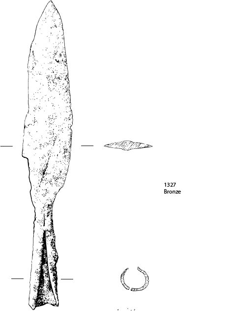
class="w-full max-w-3xl mx-auto border border-white/10 group-hover:border-[var(--color-brand-orange)] transition-all"
loading="lazy" />
Figure 4.20: Spearhead from Building 1-W Phase B, Room 2
(click to enlarge)
The fibula lay next to the skeleton’s breast and was triangular with ribbing and beading (Figure 4.22.3). Each arm of the fibula was between 5 and 6 cm long, with the diameter of the ends 2 cm wide and the narrow thin connector slightly over .5 cm. A coil, 7.5 cm long, wraps along one end and spans across to the other end. The spring was broken but repaired by wrapping the longer end around the fibula’s body. The opposite end had a small hand-shaped catch (not pictured) for the small wire. The beading had faint traces of vertical scoring, but apart from the ribbing, the rest of the object was unadorned.
Table 7: Burial Objects from Gund-i Topzawa 1C
This type of fibula falls into Stronach’s Type III 7 typology, comparable to Blinkenberg’s Type XIII, 12 typology (Blinkenberg 1926, 243ff; Stronach 1959, 197–200). Stronach describes this type as “Triangular fibulae with ribbed and beaded moulding.” This type often has a distinct hand-shaped clasp, a characteristic the Gund-i Topzawa fibula shares. It was the most common type of fibula in the Near East, found at sites across the ancient world from Syria and Palestine, Mesopotamia, to Persia (Stronach 1959, 198–200). The earliest attestations of this type, and any other fibula type, in Mesopotamia and Iran, were in the late 8th century, providing a terminus ante quem non for any context with a fibula (Muscarella 2013, 804–7). The style became increasingly popular in the 7th century, spanning the ancient world before its design largely ceased by the end of the 5th century. A similar but unrefined version survives to the Hellenistic Period (Stronach 1959, 198; Rehm 1992, 228). Two analogous fibulas of this type, from Deve Hüyük and Ur, date to the Achaemenid Period (Woolley 1914, pl. 23J; 1962, pl. 34). In Muscarella’s analysis of two different fibulas, from graves at Aššur, in Iraq, and Marlik, in Iran, he determines this type most likely dates to the 7th century (Muscarella 2013, 809–10). Given this dating, the fibula likely dates to the 7th-6th century, with the burial occurring at least some time after its production.
The other distinctive object from the burial was the straight pin and its associated ring (Figure 4.22.1). The copper-alloy pin measured 9.9 cm in length, and the ring of comparable material had a diameter of 4 cm. The rectangular profile of the pin tapered to a rounded point, but its top was squared off and crenelated. The crenelated top of the pin measured .5 cm across, while the point narrowed to .4 cm. This combination of pin and ring was common in the Achaemenid Period (Rehm 1992, 240–46). Comparable examples originate from Kamid el-Loz, Deve Hüyük, and Nippur (McCown, Haines, and Biggs 1978, pl. 60:15; Poppa 1978, pls. 7, 13, 25; Moorey 1980, fig. 16: 397-398, 405–407). Opposed to the fibula, which predated and then continued into the Achaemenid Period, this ring and pin combination begins later and continues centuries after the popularity of that fibula style wanes. That would suggest the fibula was old at the time of internment, reinforced by its broken and repaired coil, and buried with the newer pin.
Along with the fibula, pin, and ring were six other metal goods and more than 400 beads. The metal goods consisted of two small rings, two earrings, a small and large bracelet (Figure 4.23). All the metal goods were constructed from a similar copper alloy and utilized similar metallurgical techniques. The objects’ metal was bent to the desired shape, likely through forging rather than casting the final shape. The earrings’ shape (Figure 4.23.2) was roughly triangular with a flat rounded bottom, while the rings (Figure 4.23.1) were roughly circular, made from bending a single piece of metal. The larger bracelet (Figure 4.23.3), which may have served as an armlet given its position near the skeleton’s elbow, and the smaller bracelet (Figure 4.23.4) were both circles with a small gap.
The beads were made of various materials, including carnelian, bronze, frit, bronze, limestone, and clay (Figure 4.24). A series of about 28 copper alloy beads (Figure 4.24.11), each with two small striations, were arrayed in a long strand near the neck. Another bead was located near the center of the chest and resembled a cylinder seal's shape, albeit with no decorations. The beads’ placement suggests many were part of the clothing. Overall, the objects’ positioning indicates a lack of post-depositional movement and reconstructs the body's final attire. The fibula served its purpose of supporting the clothing near the breast, and the long string of copper alloy beads hung off the body, holding one or two of the small rings. The bracelet was far up the arm, near the elbow, while the pin and ring were near the feet, possibly as part of the clothing. It is worth pointing out that the ornate grave goods accompanying this body were more elaborate than would be expected from the location. Further, if they were aware of the ruins of Gund-i Topzawa, the burial location would be even prosier. Why, then, did they choose this location? Analysis of the current dataset cannot provide a definitive answer, but the following analysis of the tomb of Ghaberstan-i Topzawa demonstrates an interment of a similar period with significantly different characteristics.
Figure 4.21 not yet available
Figure 4.22 not yet available
Figure 4.23 not yet available
Figure 4.24 not yet available
Figure 4.24 not yet available
Conclusion
Three questions framed the overall analysis of Gund-i Topzawa: What was the identity and function of Building 1-W Phase B, its chronological and stratigraphic relationship of the various buildings and phases at the site, and how did its residents interact with their surrounding environment. Regarding the identity and function of Building 1-W Phase B, the architecture and stratigraphy indicate it was a two-story building functioning primarily as a domestic homestead. Its first floor was built on large bedrock outcroppings, utilizing the space to create functional areas. Notably, all of the first floor rooms seemed to have had significant, semi-permanent storage facilities, with cooking or other domestic production surrounding the storage. While the exact use of the second story was not readily apparent from the excavated material and the stratigraphy, the finds from the upper levels of the collapse and comparable ethnographies suggest those rooms were a combination of living and sleeping areas with storage of minor tools.
In addition, the building’s roof likely was covered with a combination of mud and fauna from the surrounding area, evidenced by the rich archaeobotanical material in the top level of the collapse. It was notable that the entire assemblage of ceramics and finds resembled a prototypical Urartian site, with only the absence of fine, elite goods and cups differentiating this domestic site from the royal residences. Despite a large number of grape seeds, there was no direct evidence for large or medium scale wine production, although a small vat of production cannot be ruled out. Further, there was no evidence that Building 1-W Phase B was part of a terraced series of buildings up the hill's side. The stratigraphy of the collapsed material was representative of a second story with storage of some objects on its roof. No evidence indicates a terraced structure above with collapse onto Building 1-W Phase B. During excavations, I surveyed the hillside directly above Building 1-W Phase B and, in addition to not locating any archaeological material, noted the remaining soil above bedrock was mere centimeters thick. Thus, there was an insufficient platform to create a strong foundation for buildings.
The chronology of Gund-i Topzawa is vital for establishing the length of occupation not just at this site but throughout the Sidekan area. Gund-i Topzawa’s stratigraphy, with little subsequent overbuild, made establishing a single stratigraphic chronological relationship difficult. The earliest occupation was at Building 1-E, starting as early as the 12th century. Its neighboring building dated to the 9th century, despite the two structures’ proximity and equal levels. Excavations in the eastern portion of Gund-i Topzawa did not reach lower elevations and could not confirm or deny phases predating Building 1-E’s 12th-century date. However, Building 1-W Phase A, the excavation in the modern roadway, did indicate an earlier structure that served as the foundation to the 7th-century primary occupation of Building 1-W Phase B. While we did not recover sufficient evidence to provide a date for Building 1-W Phase A, the meager remains suggest a possible Late Bronze Age or Early Iron Age date, roughly contemporary with the structures in the east. Building 1C-W’s squatter occupation and burial date a few centuries later, but none of the other material around Gund-i Topzawa indicates a substantial occupation after the destruction of Building 1-W Phase B. Gund-i Topzawa’s chronology and stratigraphy lack clear subsequent layering, typical in mound-type sites. Instead, it appears the village residents either abandoned old buildings (1-E, 2-E), creating new ones adjacently, or in some cases did build directly on top of earlier buildings (1-W, possibly 1-E). This behavior creates additional difficulty locating buried archaeological sites, as topographic clues can not guide subterranean remains. However, the behavior was a logical result for the residents, given the surrounding landscape's topography.
The specific positioning of Gund-i Topzawa in the landscape will be expanded upon further in a discussion of nearby surveyed sites, but the excavation of the site made clear that the residents adapted to the surrounding landscape. Most notably, the existence of such large quantities of bedrock jutting into the first floor and forming part of the building's architecture demonstrates not only awareness of the surroundings but an appreciation of their role in supporting their occupation. Further, the quasi-terracing of Building 1-W Phase B, with Wall 1 serving as a large retaining wall, evidences their knowledge of the ideal slope to build houses. From the available evidence, the organization of houses at Gund-i Topzawa stretched along the valley's slope rather than clustering in a central location. During the British Mandate Period in the mid-20th century CE, an ethnography recorded a nearby village of Sidekan and Gund-i Topzawa, named Rust. It was located approximately 20 km south of Gund-i Topzawa, on Hassan Beg Mountain's alternative side, with approximately 130 houses (Galloway 1958). The study primarily focused on the crops surrounding the small town and their domestic economy, with no focus on the buildings’ structure. However, the town's organization resembled the Iranian villages of Hasanabad and Aliabad, with the houses clustered together. Gund-i Topzawa’s elongated organization was likely due to the geography, which could not extend much further downslope towards the river. Overall, Gund-i Topzawa was likely indicative of the settlements that covered not just the landscape of Iron Age Sidekan but of many Iron Age intermontane landscapes.
Ghaberstan-i Topzawa
Ghaberstan-i Topzawa is a small tomb in the Sidekan area, exposed by the same road construction that revealed Gund-i Topzawa. RAP excavated the site in 2013, quickly recording the at-risk archaeological material before the cessation of the field season. Research from this section primarily comes from Dr. Danti’s report to the Kurdistan Regional Government (KRG), a brief site report in Expedition, supplementary information from excavation material and documentation, with additional analysis performed by myself (Danti 2014b; 2014a).
The aforementioned road construction initially exposed Ghaberstan-i Topzawa, as well as other sites (discussed in detail in the following Survey Chapter). The earthmovers destroyed the south side of the tomb and knocked one of the roof’s slabs into the roadway. Disturbance at Ghaberstan-i Topzawa attracted the attention of locals and, subsequently, the Directorate, as the human bones from the site fell onto the road. In addition to the disturbance at Ghaberstan-i Topzawa, many small, 1-2 m stone box burials, presumed to be Islamic burials, were also damaged by the road construction. Nearby Ghaberstan-i Topzawa, a few meters uphill, are gravestones indicating the area’s identity as an early modern cemetery. Multitudinous bones littered the road after construction moved through the area, and the Directorate collected many of them for storage. Importantly, discussions with nearby residents indicated that any people buried in the aforementioned cemetery were long before their time, and they were unaware of their identities. While the RAP team was working in Soran, Director Abdulwahab Suleiman requested we conduct an emergency excavation of the site. A small team went to the site and conducted eight days of excavations before the end of the 2013 season.
The site is ~3 km northeast of Gund-i Topzawa, along the north side of the Topzawa Çay, near where the eastern end of the valley ends. This route is crucial as it follows the main road from Sidekan up to the Kelishin Pass. Around this point in the Topzawa Valley, the width of the valley begins to narrow. Less than a kilometer to the east, the road stops following the slope of the Topzawa Valley and begins to switchback into the mountains, heading to the Kelishin Pass. This point marks the end of the Topzawa Valley and the last significant agricultural land before heading up to the peaks of the Zagros Mountains. Thus, its location was at the far outskirts of ancient habitation in the Sidekan area.
Ghaberstan-i Topzawa itself is a small stone tomb cut directly into the hillside, with intact walls on three sides, north, east, and west. The southern exposure, revealed by the construction, provided an entrance into the tomb. The walls were constructed with medium-sized, roughly worked limestone slabs, stacked slightly inward, about 2.5 m high. On top of the walls, a stone roof remained, with large boat-shaped, worked limestone slabs cantilevered over the walls. One of the central slabs contained a large crack that caused some concern for the excavation team. Throughout the excavation, the roof remained stable and, upon a brief resurvey three years later, continued to maintain its strength. Running atop the stone roof was a thin layer of red topsoil. The resulting shape of these walls and the roof is a beehive-like structure, albeit with more angular corners than a beehive’s circular shape. The tomb chamber itself was oriented 345° west of magnetic north and had a maximum height of 1.85 m. Despite the road-widening destruction, the layout of the artifacts and inhumations in the room made clear the existence of a door along the southern wall in antiquity. Excavations in the tomb’s southern area revealed a high incidence of river pebbles, notably different from ubiquitous slate and limestone throughout the rest of the tomb. Although not drawn in detail, the stratigraphy of the soil around the wall and roof of the tomb provides evidence that the walls were cut into the hillside itself, with the roof near the hill’s surface. Thus, the tomb was likely constructed by digging a hole into the gentle slope of the lower section of the hill, leaving an exposed roof and a door on the lower slope of the hill to allow access for subsequent inhumations.
Excavations inside the tomb revealed large quantities of ceramics, including intact vessels, metal artifacts, and at least 11 bodies. The tomb had three phases, an original phase of repeated internments at the tomb’s original floor (A), a period of abandonment (B), and a reuse phase (C). The tomb’s primary use occurred in Phase A. This level is separated from the phase above by a thick layer of stone collapse. Within the collapse are fragments from the phase’s uppermost burials as well as ceramics and metal artifacts. Notably, we recovered a snake-head bracelet and a copper earring within this stone collapse. Over the course of an unknown number of years, at least six bodies were interred in the tomb.
The stone collapse delineating Phase A and B crushed a skeleton in the upper portion of Phase A. Around this upper skeleton were the aforementioned bracelet and earring. Below the collapse were many skulls located around the tomb’s edges, with disarticulated associated bones. Instead, the bones were apparently stacked in piles around the skull. Apart from the two skeletons fully articulated in the center of the tomb, the remaining bodies were pushed or stacked at the tomb’s edges. Given the lack of ornaments associated with the perimeter burials, it appears the tomb was reused over many years, possibly through generations, and upon each new burial, the previous inhabitant was neatly stacked aside. Unsurprisingly, their more valuable adornments, like jewelry or other metal goods, were taken in this process. The bodies’ stacking pattern would indicate their decomposition by the time the bodies were pushed aside, as the bones’ arrangement, a stack, would be impossible as a fully intact corpse. Further evidence of continual use is the tomb’s heavily compacted red clay floor, caused by people treading on the floor over an extended period of time. Unfortunately, RAP’s osteoarcheologist could not examine the skeletons, so we currently do not know any associated information about the bodies, such as their age or sex.
Phase B provides evidence of Phase C’s much later use phase. The phase is approximately 40-60 cm thick and sterile. Deposition is fluvial and aeolian, without any large stone fragments, cultural remains, or bones. This degree of homogeneity suggests two possibilities for the abandonment phase. One, the most likely explanation, was the tomb’s blocking was largely intact after the end of its use in Phase A, and any soil came into the tomb from gaps in the blocking as well as water seeping through the construction. A second explanation would be an open doorway, but the absence of animal bones or any other material is difficult to reconcile in that interpretation. Thus, the first explanation would seem to be the most likely. This suggests that after the initial use phase, a stone blocking was placed at the entrance before eventually falling inwards and damaging much of the tomb’s contents, possibly opening the possibility for looting.
Phase C consisted of four burials articulated in their original inhumation position but disturbed by the roof collapse and construction damage. Three burials lay parallel in the chamber, arranged with their heads facing west, feet to the east, and arms extended at their side, with one burial, Skeleton 3, right below the two parallel burials. Although an Islamic burial nearby suggests an Islamic identity of these burials, Islamic burial rules dictate that the deceased lay on their side, with their right face down, facing towards the Qibla in Mecca (Khu’i 2015, v. 622). Given the destruction disturbed the skulls and the post-cranial skeletons, we could not confirm the bodies’ position. One further burial, Skeleton 4, was slumped against the north wall of the tomb and was likely the first interment in the tomb, given its stratigraphic positioning compared to the other three burials. We found no further cultural material among the burials in Phase C, and any charcoal samples collected were believed to be post-depositional. Among the human bones were animal bones, including at least two canids, although none fully articulated, suggesting an open tomb for at least some time rather than a deliberate canine burial.
The dating of the tomb relies primarily on ceramics and personal ornaments, along with a radiocarbon sample’s date. The tomb contained a serpent-headed bronze bracelet, along with beads and twisted-hoop bronze wire earrings. The bracelet has strong parallels with those in the Achaemenid cemetery at Ghalekuti and Achaemenid Village I at Susa (Ghirshman 1954, Pl. XXXIX; Haerinck 1989, fig. 4 no. 7). The complete vessels have comparanda from across the Near East. One, a spouted jar found in grasp on a skeleton, is similar to the material at Hasanlu IIIa, Yesilalic II, Pasargadae, and the Spring Cemetery at Persepolis (Ghirshman 1954, Pl. XXIV no. 6; Young, 1965, fig. 2 no. 5; Sevin 1985, fig. 4 no. 5). Another of the spouted jars parallels examples at Agrab Tepe and Hasanlu IIIa (Dyson 1965, 205,212 n. 36; Muscarella 1973, fig. 15 no. 8).
The serpent-headed bracelet and the associated earring are strongly linked to the Iron IV and Achaemenid Periods at Ghalekuti and Achaemenid Village I. Specifically, Ghirshman dates the Achaemenid Village I from the 7th-6th century (1954, 20). The bulk of the pottery has a similar dating, although some of the comparable sites date slightly earlier. Yesilalic II, for example, dates to the post-Urartian collapse, and Agrab Tepe “flourished during the seventh century BC” (Muscarella 1973, 73; Kroll 2014, 204). As the material dates to the end of the Urartian and Achaemenid Periods, the use of Phase A may have begun as early as the late 7th or 6th centuries, although possibly beginning later.
While the artifacts in the tomb’s Phase A support an Achaemenid or pre-Achaemenid date, a carbon sample from the tomb’s floor dates after the Achaemenid Period, to sometime between 359-89 B.C.E. While these dates would correspond to a Seleuco-Parthian date, none of the material matches a typical Seleuco-Parthian assemblage. One possibility is that the charcoal entered the tomb after the final interment, as the articulated burial with the associated bracelet dates centuries earlier than the range of the carbon date. Alternatively, the latest burial is contemporary with the carbon date, and the objects were reused centuries later. Regardless the final inhumations and beginning of Phase B began sometime at the end of the first millennium B.C.E.
Reuse of the tomb with subsequent burials is a characteristic that begins in the late Iron I in Luristan and spreads across the broader Near East by the Iron II Period (Haerinck 1989, 457; Sevin 2003, 187; Overlaet 2013). This architectural style of tomb, depending on its exact layout, has its origin in the Early to Middle Iron Age. In the Early Iron Age, around Lake Van, the progenitors of the Urartians first created simple cist tombs, a rectangular box with slightly arched walls dug into the ground and covered with large, flat, cobbled stones (Sevin 2003, 187–88). The second style bears several similarities to the Ghaberstan-i Topzawa construction. In addition to those tombs' rectangular shapes, the defining feature is an entranceway for the inhumation of new corpses over subsequent periods (Sevin 2003, 188). Like Ghaberstan-i Topzawa, the existing remains would be pushed towards the edges of the tomb to clear space for the new burial. This style led to the Urartian multi-chamber tombs and remained a ubiquitous style in subsequent centuries.
Comparable examples of this tomb may exist elsewhere in the Sidekan subdistrict. During Boehmer’s survey of the Sidekan area, he notes a “dolmen” in an area named Huwela, about 2 km south of Qalat Mudjesir. While his report does not have many details, only one photograph of the structure and two reported diagnostic sherds, the limited information about the structure and location provides a connection to material located in RAP’s surveys. About 4 km south of Qalaat Mudjesir, along the same hillside that Huwela must lie along, a collection of locals led us to two structures called Ghaberstan-i Kanisql. While I discuss Ghaberstan-i Kanisql in more detail in the subsequent Survey Chapter, its construction and that of Huwela bears similarities to Ghaberstan-i Topzawa. Although the sides of Kanisql resemble that at Topzawa, the roofs are constructed differently, without large blocks spanning the roof. Without further research at Ghaberstan-i Kanisql, it is impossible to parse out the relationship of these structures, but the freestanding structure provides evidence in support of the proposed southern entrance at Ghaberstan-i Topzawa.
Next to Ghaberstan-i Topzawa, directly to the east, is another structure of uncertain identity. Its best description is a “semi-subterranean pit house,” although we did not excavate it fully enough to understand stratigraphic relationships in detail. From the exposed section along the road cut, in addition to some further cleaning, there is a wall of at least five courses cut into the original surface. Between the wall and the cut contain some extra soil, presumably packed to stabilize the wall. The lower two courses of the wall were constructed of cobbled stones, and the upper three courses were a combination of limestone and slate. This eastern edge of the wall continued north into the section, curving west. In the middle of the floor of the structure was a relatively large piece of worked limestone, 50 cm tall. Above the rock are a series of clay strata mixed with slate and limestone fragments, and a surface slopes down from the direction of the tomb, filled with the slate, limestone, sand, and other soil. After the initial use of the structure, the space seems to have been filled with construction debris from the tomb. There may still be other tombs in this area, but the expedited investigation did not allow for further investigation. The limited ceramics recovered from the cleaning largely resemble that from the tomb.
Sidekan Bank
Located in the Sidekan Valley System, specifically on the outskirts of the town of Sidekan itself, is the eponymous Sidekan Bank site. Its name derives from the interrupted construction of a bank that revealed archaeological deposits in the foundation. In 2014 Abdulwahhab Suleiman, Director of Soran’s Department of Antiquities, asked RAP to conduct a site assessment. The first site inspection occurred May 14, 2014, with assistance from Dlshad Mustafa of the Antiquities Department, and documented a series of burned strata in the construction trenches. Construction on the bank had already progressed in creating a central concrete foundation, and upon arrival, the team found a large trench running around this central concrete core. Although Mr. Suleiman stopped the construction to analyze the archaeological remains, the destruction of any archaeological remains in the building core already occurred. A small RAP team conducted excavations over five days in the Summer 2014 season. Overall, the limited exposure and brief excavation time prevented the team from coming to in-depth conclusions about much, except for the site’s periodization, which helps fill out the understanding of the Sidekan area in antiquity.
The primary excavation took place over five days in June 2014. The team laid down two small excavation trenches along the eastern construction trench to link the exposed vertical stratigraphy, excavated a 2 x 2 m trench on the surface nearby to a few centimeters, and drew the eastern and northern trench’s section. Overall, the excavation yielded ca. 700 sherds, but only 27 diagnostic sherds, 13 of which have identifiable characteristics. The limited ceramic assemblage provides little help in dating the site. Fortunately, a trio of radiocarbon dates provides a firm dating for the 5th -6th-century C.E, and a small roughly preserved stamp seal confirms a 5th – 6th-century Sasanian occupation. The two small excavated areas along the eastern construction trench (technically Operations 1 & 2, although only divided by the preexisting construction trench) helped link the profile with stratigraphic and chronological dating.
Operation 1, the eastern construction trench, effectively consists of two sections, cleaned and drawn. Although there is no definitive connection between the two sides, their elevation and the distance suggest their association. Excavation along the southwestern side of the trench uncovered a floor cut into a natural conglomerate of rocky reddish-brown loam. No walls surrounded this floor, and the floor was about 60-90 cm below the modern surface. Notably, a large pithos was sunk into the floor, through the natural conglomerate, with fragments of a secondary pithos nearby. Unfortunately, the rim of the large pithos was destroyed, preventing a determination of its diameter. Regardless, the vessel was large enough to store a large number of goods. A pithos sunk into the floor is not uncommon throughout history, but at Jandavlattepa in Sasanian Central Asia, multiple pithoi were sunk into the floor of a domestic quarter (Stanco and Abdullaev 2012, 49). At another site, Ak-Tepe, also in Central Asia, pithos were sunk into the floor in an apparent storeroom (Sedov 1987, 16). Burying pithos to have the ground serve as support and using its high storage capacity was common throughout time and continued into the mid-first millennium CE.
Charcoal and other debris from a large conflagration event were on the exposed floor, including the pithos below. We recovered chunks of charcoal as large as 2 cm in diameter from this phase. Three of the samples, two from Operation 1 and one from Operation 2, were carbon dated at the University of Arizona’s AMS laboratory. The two samples in Operation 1 were located at the top of the collapse and the floor of the structure. Both date to the 5th-6th century, with sample 1043 lying on the floor and having a slightly later range. The sample in Operation 2, however, dates later, most likely between 534-610 C.E. Almost directly above this collapse layer was the original topsoil, topped by the piled debris from the construction. The nature of the debris and the lack of stone walls imply a wooden structure, possibly coated with mud along its walls or roof. The thin level of topsoil dividing the structure’s collapse layer and the surface implies a likely single occupation period at the site with continued post-depositional tilling of the soil above combined with erosion from areas uphill.
The eastern side of the construction trench was not excavated to the same extent as the western side, and thus some of the conclusions are more difficult to ascertain. No sunken pithos or floor cut into conglomerate exist on this side, although the burn layer is present here. The burn layer runs directly up against a large boulder, which may or may not be a feature of the architecture. Although unexcavated or cleaned, the north trench (Operation 2) displayed a burned stratum, ~12 m long and 20-30 cm thick, with two separate visible ash lenses. One section of the floor, directly below the burned stratum, had an opening, roughly the size of a pithos, that may have contained a vessel like that in Operation 1, although it was no longer present.
In addition to the two sections of excavation immediately along the profile created by the construction, the team laid out a 2 x 2 m excavation square on the surface nearby, Operation 3, located ~15 m from Operation 1. We laid down this small sounding to test the limits of the structure(s) at the site. Unfortunately, due to time constraints, the square was only excavated ~20 cm deep. A collection of stones, the tops of which were exposed, may indicate a wall running through the trench, but without deeper excavations, that theory cannot be confirmed. Given the excavated portions revealed burn layers far below the exposed area of Operation 3, and those excavated portions seemingly did not show substantial stone walls along the burned floor, the stones in Operation 3 should not be designated walls automatically. The low depth of these exposed stones, however, does correspond well with the thin topsoil layer observed in Operation 1 & 2.
In addition to the collected pottery, the team recovered a highly eroded stamp seal from cleaning the western section of Operation 1. The seal’s design was nearly unidentifiable, a hard to distinguish series of curved lines emanating out of another curved line that could be one of any number of signs or symbols. Fortunately, Sasanian stamp seals have distinct shapes that help identify and date them. The seal was made of a glazed frit, with a thin hole running through the body, and was a bead or simply worn with a small string in antiquity. Its shape, domed and ovaloid with a rounded back, is indicative of Sasanian seals dating to the 5th-6th centuries (Metropolitan Museum of Art and Brunner 1978, 8).
Sasanian seals and their accompanying stamps are among the most distinctive characteristic signs of occupation during this period, dating roughly from the 2nd to 7th centuries C.E. Sasanian pottery has only a handful of diagnostic types, leading to seals and other finds as the primary indicators of Sasanian occupation. Nearby sites show evidence of Sasanian occupation by distinct ceramic typologies. Notably, at Zawi Chemi Shandiar, a small site by Shanidar Cave, the upper levels, excavated in 1956, 1957, and 1960, contain “Christian Ware” (Solecki 1980, 1, 6). This pottery, both variations of fine and coarse ware, was impressed with crosses or other designs, in addition to “simple fine-line combed decorations, or single incised curvilinear designs” and glazed ceramics (Solecki 1980, 6–7). While Solecki did not connect “Christian Ware” with a typical Sasanian assemblage, these stamped designs on pottery are part of typical Sasanian ornamentation (Simpson 2013). The material at Zawi Chemi Shanidar, specifically bitumen-lined pithoi and three coins, provide connections to our work at Sidekan Bank. Unlike the pithoi at Shanidar, the Sidekan Bank pithoi are not coated with bitumen, suggesting a different use for the vessels. One of the three coins at Zami Chemi Shanidar provides a date for that site. That coin is a follis of 40 nummia, indicated by a large central M. It was produced in Constantinople by the fifth workshop of the mint, during the reigns of Anastasius I (491-518), Justin I (518-527), or Justinian I (527-565), providing a date between 498-538/9 (Solecki 1980, 71). This dating overlaps significantly with the range of carbon dates at Sidekan Bank, perhaps suggesting increased activity in this area during the 5th century. Notably, the campaign of Narses, under Emperor Maurice, was the Byzantine ruler immediately subsequent to Justinian I, suggesting the coin made its way to the region during that campaign or a continual presence by the Byzantines and their traders.
Sidekan Bank’s ceramic assemblage has few typically Sasanian diagnostic ceramics, which is unsurprising given the small collection of about a dozen diagnostic pieces and the poor understanding of Sasanian common wares (Gavagnin, Iamoni, and Palermo 2016, 155). Of these dozen sherds, none correspond well with any of the typical Sasanian typologies. Many Sasanian sherds tend to be highly decorative or elaborate. For example, Stamped Wares, discussed above, are the most diagnostic pieces of the period (Simpson 2013). Further, so-called “Corrugated-rim jars” are another primary signifier of Sasanian occupation. Sasanians decorated these rims with multiple bands of ribbing, often with additional incisions or other decorations (Puschnigg 2006, 135, 223; Stanco and Abdullaev 2012, 51; Simpson 2013, 99). In contrast, all the rims of comparably sized vessels at Sidekan Bank are plain. Other typical Sasanian wares, like “Honeycomb Ware,” named for its heavily pocketed surface, are absent in the assemblage (Simpson 2013, 102). In addition to these types, a majority of diagnostic Sasanian wares are glazed, none of which is evident at this site (Kennet 2004).
Sasanian occupation at a relatively flat site, like Zawi Chemi Shanidar, corresponds well to the theory of an increase in nomadism and pastoralism during the period (Wilkinson 1995, 69–71). Further, the Land of Nineveh survey, to the west, indicated that multiple Sasanian sites were new foundations, not built on top of the remains of earlier settlements like in previous periods (Gavagnin, Iamoni, and Palermo 2016, n. 27). If Sasanians built semi-nomadic settlements on new foundations, these were often modest structures. At Jandavlattepa, structures made of rammed earth, mudbrick, and small wooden circular buildings provide evidence for more ephemeral construction (Stanco and Abdullaev 2012, 46). Given the type of excavation at Sidekan Bank, largely cleaning sections versus controlled vertical excavations, the team would not have been able to identify postholes suggestive of a wooden building. The basic walls, large storage pithos, and lack of elite wares, along with its location at the flat portion of the valley, directly in the core agricultural zone, suggest Sidekan Bank was not a primary habitation area but rather a gathering and storage loci for the surrounding farming and pastoral activities.
While one interpretation of Sidekan Bank is of a small site on the outskirts of a large town in the area of modern Sidekan, two pieces of evidence refute that. One, conversations with locals in Sidekan and limited survey in the streets suggest there is no sizeable archaeological presence in the core of the town itself. A large presumed mound near the center of town, east of Sidekan Bank, was later cut by construction and revealed to be a natural feature. The only archaeological remains were large pithoi sunk into the surface, of a different, far more orange, ware than the pithoi at Sidekan Bank. Second, an intensive survey of the rolling hillside directly adjacent to Sidekan Bank, to the northeast, recovered very few sherds.
Concurrent with the excavation, I conducted an intensive fieldwalking survey by snaking transects along the hillside around Sidekan Bank. This area of modern Sidekan was bounded on one side by the modern town to the north and the Sidekan River to the south. Specifically, the rolling hillside abruptly ends with a deep cut leading down to the riverbed below. While I primarily surveyed the hillside, the limited examination of this cut to look for further possible sherds moved by post-depositional processes did not locate any significant evidence. These transects resulted in less than one dozen sherds, none of which were diagnostic. Further, the pattern of the sherds’ findspots did not reveal any arrangement suggesting a more significant settlement nearby.
Combining historical information discussed in Chapter 2, the chronological dating of Sidekan Bank may align closely with the campaign to Aniseni by the Byzantine general Narses and Sasanian king Xurso II. Records from Byzantine historians place that campaign in the year 589 CE. While the site does not show widespread destruction like that at Gund-i Topzawa, the small burn layer could indicate the army’s occupation while moving to the Kelishin Pass. One of the three radiocarbon samples (1032) may correspond to that campaign, with an 89.8% probability of falling between 534-610 CE. This does not necessarily suggest the Byzantine forces destroyed the site but rather their presence coincided with the occupation at this site.
Given the focus of the dissertation of the Iron Age, specifically Muṣaṣir, the excavations at Sidekan Bank may seem out of place. Several characteristics of this site, contrasted to the sites mentioned above, are important for understanding and interpreting occupation in the region. Sidekan Bank is the only excavated site in the Sidekan subdistrict that does not date to the Iron Age or Late Bronze Age. It serves to establish that settlement in this area did not wholly disappear, despite the paucity of historical records. Relatedly, the pottery excavated at Sidekan Bank is minimal and nondistinctive. During survey, the absence of pottery on the surface in Sidekan greatly complicates locating sites and dating (Chapter 5). The nondescript pottery at Sidekan Bank, established as Sasanian only though related finds and carbon dating, would not assist in dating sites if found on the surface. The Sasanian pottery in Sidekan bears more similarities to the Iron Age ceramics than the classic Sasanian diagnostics; thus, it is important context when attempting to date sites with pottery alone. Further, the nomadic or ephemeral settlement at Sidekan Bank, in the center of the central agricultural basin in Sidekan, is indicative of the settlement types in the lowlands of Sidekan as well as the possibility of changing settlement patterns into nomadism after the Iron Age.